

Ä |
|
EXHAUST SYSTEM AND INTAKE MANIFOLD 11 - 13 |
|
Fig. 8 Camshaft Sensor and Fuel Injectors Wiring
Connectors
Fig. 9 Fuel Supply and Return Hose Connections
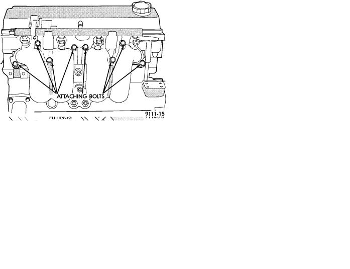
(12) Remove 8 intake manifold screws and washer assemblies and remove intake manifold (Fig. 10).
INSTALLATION
Before installing manifold. Refer to Cleaning and Inspection of this section to check manifold for damage.
(1)Install new intake manifold gasket and intake
manifold onto cylinder head and tighten fasteners to 23 NIm (200 in. lbs.) torque (Fig. 10).
(2)Install PCV Breather/Separator box and vacuum harness assembly. Connect brake booster, vacuum vapor harness and vacuum hose to fuel pressure regulator (Fig. 7).
(3)Inspect quick connect fittings for damage, replace if necessary Refer to Fuel System, Group 14 for procedure. Lube tube with clean 30w engine oil, Connect fuel supply and return hoses to chassis tube assembly. Check connection by pulling on connector to insure it locked into position (Fig. 9).
(4)Connect Fuel Injector (Fig. 8), and Charge Temperature Sensor wiring connectors (Fig. 7).
Fig. 10 Intake Manifold Attaching Bolts.
INTAKE MANIFOLD
(5)Connect Automatic Idle Speed (AIS) and Throttle Position Sensor (TPS) wiring connectors (Fig. 6).
(6)Connect vacuum hoses to throttle body (Fig. 5).
(7)Install intercooler to throttle body hose and clamp. Torque clamp to 3 NIm (30 in. lbs.) (Fig. 5).
(8)Connect accelerator and speed control cables (Fig. 4).
(9)Install DIS Ignition Coil pack. Tighten fasteners to 12 NIm (105 in. lbs.) torque (Fig. 3).
(10)Install upper radiator hose and spring clamps (Fig. 2). Fill Cooling System, Refer to Cooling System, Group 7.
(11)Install fresh air duct to air filter housing. In-
stall inlet hose assembly to Intercooler. Tighten clamp to 3 NIm (30 in. lbs.) torque (Fig. 1).
(12)Connect negative battery cable.
(13)With the DRB II use ASD Fuel System Test to pressurize system to check for leaks.
CAUTION: When using the ASD Fuel System Test, the Auto Shutdown (ASD) relay will remain energized for 7 minutes or until the ignition switch is turned to the OFF position, or Stop All Test is selected.
TURBOCHARGER
REMOVAL
Turbochargers are removed from below the vehicle. Cylinder head removal for component accessibility is not required.
(1)Disconnect negative battery cable. Remove Air Cleaner assembly (Fig. 1).
(2)From Above: Remove front engine mount through bolt and rotate engine (Top) forward away from cowl. Refer to Engine Removal in Engine, Group 9.
(3)Remove Air Cleaner Support (Fig. 1).

11 - 14 EXHAUST SYSTEM AND INTAKE MANIFOLD |
|
Ä |
|
(4)Disconnect 02 sensor lead wire and vacuum
lines.
(5)Separate coolant return line from water box and turbocharger housing (Fig. 11). Remove return line from turbocharger.
Fig. 11 Coolant Tube Routing
Fig. 12 Turbocharger Attaching Nuts
(6)Separate oil feed line from turbocharger housing (Fig. 12).
(7)Remove three (two upper and one lower driver's side) nuts retaining turbocharger to manifold (Fig. 12).
(8)From Below: Remove right front wheel and tire assembly.
(9)See Suspension, Group 2, and remove right driveshaft assembly. Air deflector may need to be removed from crossmember.
(10)Separate oil drain back tube fitting from turbocharger housing and remove fitting and hose (Fig. 13).
(11)Remove turbocharger to block support bracket (Fig. 13).
(12)Remove one remaining turbocharger to manifold retaining nut (Fig. 12).
Fig. 13 Oil Return Tube and Support Bracket
(13)Disconnect articulated exhaust pipe joint from turbocharger housing.
(14)Remove turbocharger coolant inlet line assembly from engine (Fig. 11).
(15)Lift turbocharger off manifold mounting studs and lower assembly down and out of vehicle.
EXHAUST MANIFOLD
REMOVAL
Remove 9 exhaust manifold retaining fasteners and remove exhaust manifold (Fig. 14).
Fig. 14 Exhaust ManifoldÐTurbo III Engine
CLEANING AND INSPECTION
(1)Discard gasket and clean all gasket surfaces of manifolds and cylinder head.
(2)Test manifold gasket surfaces for flatness with straight edge. Surface must be flat within 0.15 mm per 300 mm (.006 in. per foot) of manifold length.
(3)Inspect manifolds for cracks or distortion. Replace manifold if necessary.
EXHAUST MANIFOLD
INSTALLATION
(1) Install new manifold gasket. DO NOT APPLY SEALER.

Ä |
|
EXHAUST SYSTEM AND INTAKE MANIFOLD 11 - 15 |
|
(2) Set exhaust manifold in place. Tighten retaining nuts and bolt, starting at center and progressing outward in both directions to 23 NIm (200 in. lbs.) torque. Repeat this procedure until all fasteners are at specified torque (Fig. 14).
pipe to be combined with the rear bank exhaust at the exhaust outlet to the exhaust pipe (Fig. 2).
INTAKE PLENUM/MANIFOLD
REMOVAL
TURBOCHARGER
INSTALLATION
(1)Position turbocharger on exhaust manifold. Apply antiseize compound to threads and install the
lower (passenger side) retaining nut (Fig. 12). Tighten nut to 54 NIm (40 ft. lbs.) torque.
(2)Apply thread sealant to lower (inlet) coolant line fitting and install fitting into turbocharger housing (Fig. 11).
(3)Install lower coolant line assembly to engine (Fig. 11).
(4)Install oil drain back tube and fitting (with new gasket) to turbocharger housing (Fig. 13).
(5)Install turbocharger to block support bracket
and install screws finger tight (Fig. 13). Tighten block screw FIRST to 54 NIm (40 ft. lbs.) torque, then tighten screw to turbocharger housing to 27 NIm (20 ft. lbs.) torque.
(6)Reposition exhaust pipe. Tighten articulated joint shoulder bolts to 28 NIm (250 in. lbs.) torque.
(7)See Suspension, Group 2, and install right driveshaft and wheel and tire assembly. Install air deflector on crossmember.
(8)From Above: Install three turbocharger to manifold retaining nuts. Tighten to 54 NIm (40 ft. lbs.) torque (Fig. 12).
(9)Reconnect 02 sensor electrical connection and vacuum lines.
(10)Attach oil feed line to turbocharger bearing housing. Tighten fitting to 14 NIm (125 in. lbs.) torque (Fig. 12).
(11)Install coolant line and tighten fittings to 41 NIm (30 ft. lbs.) torque (Fig. 11).
(12)Install Air Cleaner support (Fig. 1).
(13)Align front engine mount in crossmember bracket. Install through bolt and tighten to 54 NIm (40 ft. lbs.) torque.
(14)Install Air Cleaner assembly (Fig. 1).
(15)Fill Cooling System. Refer to Cooling System, Group 7 for procedure.
(1)Perform fuel system pressure release procedure
(before attempting any repairs).
(2)Disconnect negative battery cable. Drain cooling system. See Cooling System, Group 7.
(3)Remove air cleaner to throttle body hose (Fig.
4).
FUEL SYSTEM PRESSURE RELEASE PROCEDURE
The MPI fuel system is under a constant pressure of about 330 kPa (48 psi). Before servicing the fuel pump, fuel lines, fuel filter, throttle body or fuel injector, the fuel system pressure must be released.
(a)Loosen fuel filler cap to release fuel tank pres-
sure.
(b)Disconnect injector wiring harness from engine harness.
(c)Connect a jumper wire to ground terminal Number 1 of the injector harness (Fig. 3) to engine ground.
(d)Connect a jumper wire to the positive terminal Number 2 of the injector harness (Fig. 3) and touch the battery positive post for no longer than 5 seconds. This releases system pressure.
(e)Remove jumper wires.
(f)Continue fuel system service.
INTAKE/EXHAUST MANIFOLD SERVICEÐ3.0L ENGINE
The intake system has a large air intake plenum of aluminum alloy and a cross type intake manifold (Fig. 2).
The exhaust manifolds are made of ductile cast iron with the front bank and rear bank independent of each other. The exhaust from the front bank exhaust manifold is led through on exhaust crossover
Fig. 1 Injector Harness Connector
(4)Remove throttle cable and transaxle kickdown linkage (Fig. 5).
(5)Remove automatic idle speed (AIS) motor and throttle position sensor (TPS) wiring connectors from throttle body (Fig. 6).
(6)Remove vacuum hose harness from throttle body (Fig. 6).

11 - 16 EXHAUST SYSTEM AND INTAKE MANIFOLD |
|
Ä |
|
Fig. 2 Intake and Exhaust ManifoldsÐ 3.0L Engine
(7)Remove PCV and Brake booster hoses from Air Intake Plenum.
(8)Remove Ignition Coil from Intake Plenum (Fig.
7).
(9)Remove wiring connectors from coolant temperature sensor (Fig. 8).
(10)Remove vacuum connections from Air Intake Plenum vacuum connector.
(11)Remove fuel hoses from fuel rail (Fig. 8).
WARNING: WRAP SHOP TOWELS AROUND HOSES TO CATCH ANY GASOLINE SPILLAGE.
(12)Remove (8) Fasteners from Air Intake Plenum to Intake Manifold (Fig. 9).
(13)Remove Air Intake Plenum (Fig. 10).
(14)Cover intake manifold with suitable cover when servicing.
(15)Remove vacuum hoses from fuel rail and fuel pressure regulator (Fig. 11).
(16)Disconnect Fuel Injector wiring harness from engine wiring harness (Fig. 12).
(17)Remove fuel pressure regulator attaching bolts and remove regulator from rail (Fig. 13). Be careful not to damage the rubber injector O-rings upon removal from the ports.
(18)Remove fuel rail attaching bolts and lift fuel rail assembly from intake manifold.
(19)Separate radiator hose from thermostat housing and heater hose from heater pipe.
(20)Remove (8) nut and washer assemblies and remove intake manifold (Fig. 1).
Fig. 3 Throttle Body Assembly 3.0L
INSPECTION
Check for:
²Damage and cracks of each section (Fig. 13).
²Clogged water passages in end cross overs.