

Ä |
|
EXHAUST SYSTEM AND INTAKE MANIFOLD 11 - 17 |
|
² Check for distortion of the cylinder head mounting surface using a straightedge and thickness gauge (Fig. 14). Refer to (Fig. 15) for Specifications.
Fig. 4 Throttle Cable Attachment
INSTALLATION
(1)Position new intake manifold gaskets on cylinder head and install intake (cross) manifold.
(2)Install (8) nuts and washers and tighten in several steps in order shown in (Fig. 16) to 20 NIm (174 in. lbs.).
(3)Make sure the injector holes are clean and all plugs have been removed.
(4)Lube injector O-ring with a drop of clean engine oil to ease installation.
(5)Put the tip of each injector into their ports. Push the assembly into place until the injectors are seated in the ports.
(6)Install the (3) fuel rail attaching bolts and torque to 13 NIm (115 in. lbs.).
(7)Install fuel pressure regulator onto fuel rail.
Install attaching bolts to intake manifold. Torque regulator nuts and bracket bolts to 10 NIm (95 in. lbs.) (Fig. 12).
(8)Install fuel supply and return tube hold-down
bolt and the vacuum crossover tube hold-down bolt and torque to 10 NIm (95 in. lbs.).
(9)Connect fuel injector wiring harness to engine wiring harness (Fig. 11).
(10)Connect vacuum harness to fuel pressure regulator and fuel rail assembly (Fig. 10).
(11)Remove covering from lower intake manifold and clean surface.
(12)Place intake manifold gaskets with beaded sealant side up on lower manifold. Put air intake in
place. Install attaching fasteners (8) and tighten in several steps in sequence shown (Fig. 17) to 13 NIm (115 in. lbs.).
(13)Connect fuel line to fuel rail (Fig. 7). Torque hose clamps to 1 NIm (10 in. lbs.).
Fig. 5 Electrical and Vacuum Connections to Throttle Body
Fig. 6 Ignition Coil Removal
(14) Connect vacuum harness to air intake plenum.
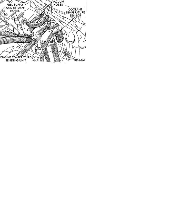
Fig. 7 Coolant Temperature Sensor Electrical Con-
nections

11 - 18 EXHAUST SYSTEM AND INTAKE MANIFOLD |
|
Ä |
|
Fig. 8 Air Intake Plenum to Intake Manifold Attaching Bolts
(15)Connect coolant temperature sensor electrical connector to sensor (Fig. 7).
(16)Connect PCV and brake booster supply hose to intake plenum.
(17)Connect automatic idle speed (AIS) motor and throttle position sensor (TPS) electrical connectors (Fig. 5).
Fig. 11 Fuel Injector Wiring Harness
(18)Connect vacuum vapor harness to throttle body (Fig. 5).
(19)Install throttle cable and transaxle kickdown linkage (Fig. 4).
(20)Install air inlet hose assembly (Fig. 3).
(21)Install radiator to thermostat housing hose and heater hose to heater pipe nipple.
(22)Fill cooling system, see Refilling System in Cooling, Group 7.
(23)Connect negative battery cable.
(24)With the DRB II use ASD Fuel System Test to pressurize system to check for leaks.
CAUTION: When using the ASD Fuel System Test, the Auto Shutdown (ASD) relay will remain energized for 7 minutes or until the ignition switch is turned to the OFF position, or Stop All Test is selected.
Fig. 9 Removing Air Intake Plenum
Fig. 10 Vacuum Connections for Fuel Rail and Fuel Pressure Regulator
Fig. 12 Fuel Pressure Regulator to Fuel Rail Assembly
EXHAUST MANIFOLDS
REMOVAL
(1)Raise vehicle and disconnect exhaust pipe from rear (cowl side) exhaust manifold at articulated joint.
(2)Disconnect Oxygen Sensor lead wire at the rear exhaust manifold (Fig. 18).

Ä |
|
EXHAUST SYSTEM AND INTAKE MANIFOLD 11 - 19 |
|
Fig. 15 Intake Plenum and Cylinder Head Mounting
Surface Specifications
Fig. 13 Check Intake (Cross) Manifold Mounting
Surface
Fig. 14 Check Intake Plenum Mounting Surfaces
(3)Remove bolts attaching cross-over pipe to manifold (Figs. 2 and 19).
(4)Remove nuts attaching rear manifold to cylinder head and remove manifold.
Fig. 16 Nut Tightening Sequence for Intake (Cross) Manifold
Fig. 17 Intake Plenum Tightening Sequence
(5)Lower vehicle and remove screws attaching front heat shield to front manifold (Fig. 2).
(6)Remove bolts fastening crossover pipe to front exhaust manifold and nuts fastening manifold to cylinder head. Remove assemblies.
INSPECTION
Inspect exhaust manifolds for damage or cracks and check distortion of the cylinder head mounting

11 - 20 EXHAUST SYSTEM AND INTAKE MANIFOLD |
|
Ä |
|
INSTALLATION
Install the gaskets with the numbers 1-3-5 embossed on the top on the rear bank and those with numbers 2-4-6 on the front (Radiator side) bank (Fig. 21).
(1) Install rear exhaust manifold and tighten attaching nuts to 20 NIm (175 in. lbs.).
(2) Attach exhaust pipe to exhaust manifold and tighten shoulder bolt to 28 NIm (250 in. lbs.)
(3) Attach crossover pipe to exhaust manifold and tighten bolt to 69 NIm (51 ft. lbs.)
(4) Connect heated oxygen sensor lead (Fig. 18).
(5) Install front exhaust manifold and attach exhaust crossover.
(6) Install front manifold heat shield and tighten
attaching screws to 15 NIm (130 in. lbs.) (Fig. 2).
Fig. 18 Separate Articulated Joint, Disconnect Oxygen Sensor Wire
Fig. 19 Crossover Pipe
Fig. 20 Check Exhaust Manifold Mounting Surface
surface and exhaust crossover mounting surface with a straightedge and thickness gauge (Fig. 20).
Fig. 21 Identify Exhaust Manifold Gaskets
INTAKE/EXHAUST MANIFOLD SERVICEÐ3.3/3.8L ENGINES
INTAKE MANIFOLD
REMOVAL
(1)Perform fuel system pressure release procedure,
Before attempting any repairs.
(2)Disconnect negative battery cable. Drain cooling system. Refer to Cooling System, Group 7.
FUEL SYSTEM PRESSURE RELEASE PROCEDURE
The MPI fuel system is under a constant pressure of about 330 kPa (48 psi). Before servicing the fuel pump, fuel lines, fuel filter, throttle body or fuel injector, the fuel system pressure must be released.
(a)Loosen fuel filler cap to release fuel tank pres-
sure.
(b)Disconnect injector wiring harness from engine harness.
(c)Connect a jumper wire to ground terminal Number 1 of the injector harness (Fig. 1) to engine ground.
Ä |
|
EXHAUST SYSTEM AND INTAKE MANIFOLD 11 - 21 |
|
(d)Connect a jumper wire to the positive terminal Number 2 of the injector harness (Fig. 1) and touch the battery positive post for no longer than 5 seconds. This releases system pressure.
(e)Remove jumper wires.
(f)Continue fuel system service.
Fig. 1 Injector Harness Connectors
(3)Remove air cleaner to throttle body hose assembly (Fig. 2).
(4)Remove throttle cable (Fig. 3). Remove wiring harness from throttle cable bracket.
(5)Remove automatic idle speed (AIS) motor and throttle position sensor (TPS) wiring connectors from throttle body (Fig. 4).
Fig. 2 Throttle Body AssemblyÐ3.3/3.8L Engines
(e)Remove jumper wires.
(f)Continue fuel system service.
(6)Remove vacuum hose harness from throttle body (Fig. 4).
(7)Remove PCV and brake booster hoses from air intake plenum (Fig. 5).
Fig. 3 Throttle Cable Attachment
Fig. 4 Electrical and Vacuum Connection to Throttle Body
(8)Remove EGR tube flange from intake plenum (Fig. 5).
(9)Disconnect Charge Temperature Sensor electrical connector. Remove vacuum harness connectors from Intake Plenum (Fig. 5).
(10)Remove cylinder head to intake plenum strut (Fig. 5).
11 - 22 EXHAUST SYSTEM AND INTAKE MANIFOLD |
|
Ä |
|
Fig. 5 Electrical and Vacuum Connections To Intake
Manifold
Fig. 6 MAP Sensor Electrical Connector
(11)Disconnect MAP Sensor and heated Oxygen Sensor electrical connection. Remove the engine mounted ground strap (Fig. 6).
(12)Remove the fuel hose quick connect fittings from the fuel rail using an open end wrench to push in on the plastic ring located on the end of the fittings. Gently pull the fittings from the fuel rail (Fig. 7).
WARNING: WRAP A SHOP TOWEL AROUND HOSES TO CATCH ANY GASOLINE SPILLAGE.
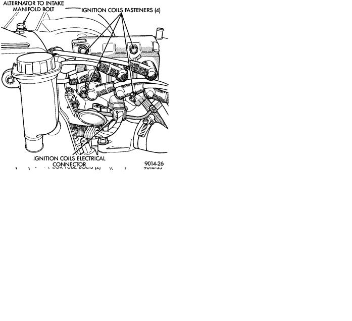
(13)Remove direct ignition system (DIS) coils and alternator bracket to intake manifold bolt (Fig. 8).
(14)Remove intake manifold bolts and rotate manifold back over rear valve cover (Fig. 9).
Fig. 7 Quick Connect Fuel Fittings to Fuel Rail
Fig. 8 Ignition Coils
(15)Cover intake manifold with suitable cover when servicing (Fig. 10).
(16)Remove vacuum harness connector from Fuel Pressure Regulator.
(17)Remove fuel tube retainer bracket screw and fuel rail attaching bolts (Fig. 10). Spread the retainer bracket to allow fuel tube removal clearance.
(18)Remove fuel rail injector wiring clip from the alternator bracket (Fig. 11).
(19)Disconnect cam sensor, coolant temperature sensor, and engine temperature sensors.
(20)Remove fuel injector wiring clip from intake manifold water tube.
(21)Remove fuel rail. Be careful not to damage the rubber injector O-rings upon removal from their ports (Fig. 12).