

Part III - Well stimulation methods
.pdfHydraulic fracturing
Absolute and effective stresses: |
|
|
|
Stress and pressure scale |
p |
||
|
|||
|
Biot (poroelastic) constant: |
||
Depth |
1 |
K |
1 cr |
|
|
K r |
cb |
|
|
||
p |
|
|
|
Part III - Well stimulation methods |
11 |

Hydraulic fracturing
Tensile failure of formation:
p f To
Breakdown pressure after Terzaghi:
pbd 3 h H To p
Part III - Well stimulation methods |
12 |
Hydraulic fracturing
Hook’s law (1D case)
E1
Hook’s law in 3D case
i E1 i j k
Part III - Well stimulation methods |
13 |

Hydraulic fracturing
In case of effective stresses (3D case)
|
|
|
|
|
|
1 |
|
|
|
|
|
|
|
|
(1) |
|
|||||
|
|
i |
|
|
|
|
|
|
|
||||||||||||
|
|
|
|
|
E |
i |
|
j |
|
k |
|
|
|
|
|
|
|
||||
|
|
|
|
|
|
|
|
|
|
|
|
|
|
|
|
|
|
|
|
||
Assuming no lateral displacement, i.e.: |
|
|
|
|
|
|
|
||||||||||||||
i j h 0 |
|
i j h |
|
|
|
|
|
||||||||||||||
0 |
1 |
|
|
|
|
|
|
|
|
|
|
|
|
|
|
|
|
|
|
(2) |
|
|
|
|
|
|
|
|
h |
|
|
|
v |
|
|
||||||||
|
|
|
|
|
|
|
|
|
|
|
|
||||||||||
|
|
|
|
|
|
|
|
|
|
|
|||||||||||
E |
h h |
v |
|
|
|
|
1 |
|
|
|
|
|
|||||||||
|
|
|
|
|
|
|
|
|
|
|
|
|
|
|
|
|
|||||
|
|
|
|
|
|
|
|
|
|
|
|
|
|
|
|
|
|
|
|
|
|
Part III - Well stimulation methods |
14 |

Hydraulic fracturing
Relationships between horizontal and vertical effective and normal stresses:
h |
|
|
|
v |
|
|
|
||||
|
|
|
|||
|
1 |
|
|
||
|
|
|
|
|
|
h |
|
|
v |
1 2 |
p |
|
|
1 |
|||
1 |
|
|
|||
|
|
|
|
|
|
Part III - Well stimulation methods |
15 |

Hydraulic fracturing
Failure diagram (after Mohr)
|
|
|
|
|
|
|
|
|
|
|
|
|
|
|
|
|
|
|
|
|
|
|
|
|
|
|
|
|
|
|
|
|
|
|
|
|
- p p |
|
|
|
|
|
|
p |
|
|
|
-T0 |
|
|
- p |
max |
|
|
|||||||||
|
min |
|
minmin |
|
|
maxmax |
|
|
|
||||||
Part III - Well stimulation methods |
16 |

Hydraulic fracturing
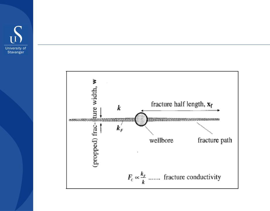
Rock mechanic aspects of fracture propagation
The entire fracture design depends on the following fracturing parameters:
Fracture half-length, xf
Fracture width, w
Fracture conductivity, kfw/k
Fracture height, hf
Azimuth, shape or symmetry about the wellbore
Part III - Well stimulation methods |
17 |
Hydraulic fracturing
Rock mechanic aspects of fracture propagation
Part III - Well stimulation methods |
18 |
Hydraulic fracturing
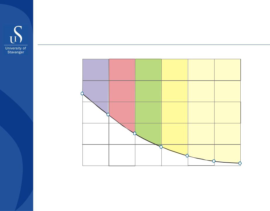
Desired fracture half-length for different formation permeabilities
|
5.0 |
|
|
|
|
Near |
|
|
|
Extremely |
Very |
Tight |
|
Conventional |
|
||
|
|
tight |
tight |
|
tight |
|
||
ft |
4.0 |
|
|
|
|
|||
|
|
|
|
|
|
|
||
1000 |
|
|
|
|
|
|
|
|
|
|
|
|
|
|
|
|
|
length, |
3.0 |
|
|
|
|
|
|
|
|
|
|
|
|
|
|
|
|
half |
2.0 |
|
|
|
|
|
|
|
|
|
|
|
|
|
|
|
|
Fracture |
1.0 |
|
|
|
|
|
|
|
|
|
|
|
|
|
|
|
|
|
0 |
|
|
|
|
|
|
|
|
10 -4 |
10 -3 |
|
10 -2 |
10 -1 |
10 0 |
10 1 |
10 2 |
In-situ gas permeability, md
Part III - Well stimulation methods |
19 |

Hydraulic fracturing
Material balance equation for fracture propagation
x f |
qit p |
|
|
2h f w CL rp |
t p |
||
|
|||
|
|
Fracture |
|
CL – leak-off coefficient |
|
||
rp = A/Af |
|
Reservoir |
|
|
A |
||
Part III - Well stimulation methods |
20 |