


Roll Modes
•Roll Hold (default mode) — Holds the current aircraft roll attitude or rolls the wings level, depending on the commanded bank angle
•HeadingSelect—CapturesandtrackstheSelected Heading
•Navigation (GPS, VOR, LOC) — Captures and tracks the selected navigation source
•Backcourse — Captures and tracks a localizer signal for backcourse approaches
•Approach (GPSa, VAPP, LOC) — Captures and tracks the selected navigation source with greater sensitivity for approach
•Go Around — Commands a constant pitch angle and wings level while in the air
The following table relates each roll mode to its respective control and annunciation. Refer to the pitch modes section for information regarding Go Around and Takeoff Modes.
SECTION 6 – AUTOMATIC
FLIGHT CONTROL
The CWS Button does not change lateral references for Heading Select, Navigation, Backcourse, or Approach modes. The autopilot guides the aircraft back to the Selected Heading/Course upon release of the CWS Button.
Roll Hold Mode (ROL)
NOTE: If Roll Hold Mode is activated as a result of a mode reversion, the flight director rolls the wings level.
Whentheflightdirectorisactivated(theFDorAPKey is pressed), Roll Hold Mode is selected by default. This modeis annunciated as‘ROL’intheAFCSStatusBox. The current aircraft bank angle is held, subject to the bank angle conditions listed in Table 6-3.
Roll Mode |
Control |
Annunciation |
|
Roll Hold |
(default) |
ROL |
|
Heading Select |
HDG Key |
HDG |
|
Navigation, GPS Arm/Capture/Track |
|
GPS |
|
|
|
|
|
Navigation,VOR Enroute Arm/Capture/Track |
NAV Key |
VOR |
|
Navigation, LOC Arm/Capture/Track |
LOC |
||
|
|||
(No Glideslope) |
|
||
|
|
||
Backcourse Arm/Capture/Track |
BC Key |
BC |
|
Approach, GPS Arm/Capture/Track |
|
GPSa |
|
|
|
|
|
Approach,VOR Arm/Capture/Track |
APR Key |
VAPP |
|
Approach, ILS Arm/Capture/Track |
LOC |
||
|
|||
(Glideslope Mode automatically armed) |
|
||
|
|
||
Go Around (in air) |
GA Switch |
GA |
|
Table 6-2 Roll Modes |
|
||
Garmin G1000 Cockpit Reference Guide for the Cessna Nav III |
6-17 |
SECTION 6 – AUTOMATIC
FLIGHT CONTROL
Figure 6-20 Roll Hold Mode Annunciation
Bank Angle |
Flight Director Response |
< 6° Rolls wings level
6° to 22° Maintains current aircraft roll attitude
> 22° Limits bank to 22°
Table 6-3 Roll Hold Mode Responses
Changing the Roll Reference
TherollreferencecanbechangedbypressingtheCWS
Button, establishing the desired bank angle, then releasing
the CWS Button.
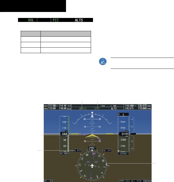
Heading Select Mode (HDG)
Heading Select Mode is activated by pressing HDG Key. Heading Select Mode acquires and maintains the Selected Heading. The Selected Heading is shown by a light blue bug on the HSI and in the box to the upper left of the HSI.
Changing the Selected Heading
NOTE: Pressing the HDG Knob synchronizes the Selected Heading to the current heading.
The Selected Heading is adjusted using theHDGKnob on either display. Pressing the CWS Button and handflying the aircraft does not change the Selected Heading. The autopilot guides the aircraft back to the Selected Heading upon release of the CWS Button.
Heading Select Mode Active |
Pitch Hold Mode Active |
Command Bars
Track Selected
Heading
Selected
Heading
Selected
Heading
Bug
Figure 6-21 Heading Select Mode
6-18 |
Garmin G1000 Cockpit Reference Guide for the Cessna Nav III |

TurnsarecommandedinthesamedirectionasSelected Heading Bug movement, even if the bug is turned more than 180° from the present heading (e.g., a 270° turn to the right). However, Selected Heading changes of more than 340° at a time result in turn reversals.
Navigation Mode (GPS, VOR, LOC)
NOTE:Theselectednavigationreceivermusthave a validVOR or LOC signal or active GPS course for the flight director to enter Navigation Mode.
Pressing the NAV Key selects Navigation Mode. Navigation Mode acquires and tracks the selected navigation source on the HSI (GPS, VOR, LOC). The flight director follows GPS roll steering commands when GPS is the selected navigation source.
SECTION 6 – AUTOMATIC
FLIGHT CONTROL
When the HSI is coupled to VOR or LOC, the flight director creates roll steering commands from the Selected Course and deviation. Navigation Mode can also be used to fly non-precision GPS and LOC approaches where glideslope capture is not required.
If the Course Deviation Indicator (CDI) shows greater than one dot when the NAV Key is pressed, the selected modeisarmed. Thearmedannunciationappearsinwhite to the left of the active roll mode. For cases where the projected course is offset a large distance from the present course for turn anticipation, GPS Navigation Mode can be activated with crosstrack error up to 10 nm when the NAV Key is pressed.
Figure 6-23 GPS Navigation Mode Armed
GPS Navigation |
Flight Level |
Altitude Hold |
|||
Change Mode |
|||||
Mode Active |
Mode Armed |
||||
Active |
|||||
|
|
|
|||
|
|
|
|
|
|
Command Bars
Indicate Left Turn to
Track GPS Course and Climb to Intercept Selected Altitude
GPS is Active Naviga-
tion Receiver on HSI
Selected Course
Figure 6-22 Navigation Mode |
|
Garmin G1000 Cockpit Reference Guide for the Cessna Nav III |
6-19 |

SECTION 6 – AUTOMATIC
FLIGHT CONTROL
When the CDI has automatically switched from GPS to LOC during a LOC/ILS approach, GPS Navigation Mode remains active, providing GPS steering guidance until the localizer signal is captured. LOC Navigation Mode is armedinanticipationoflocalizersignalcaptureiftheAPR Key is not pressed prior to the automatic source switch.
If Navigation Mode is active and either of the following occur, the flight director reverts to Roll Hold Mode (wings rolled level):
•Different VOR is tuned while in VOR Navigation Mode (VOR Navigation Mode reverts to armed)
•Navigation source is manually switched
•Localizersignalisnotcapturedbythefinalapproach fix (FAF) while in LOC Navigation Mode
Changing the Selected Course
The Selected Course on the PFD is controlled using the CRS Knob. Pressing the CWS Button and hand-flying the aircraft does not change the Selected Course while in Navigation Mode. The autopilot guides the aircraft back totheSelectedCourse(orGPSflightplan) whenthe CWS Button is released.
Approach Mode (GPSa, VAPP, LOC)
NOTE:Theselectednavigationreceivermusthave a valid VOR or LOC signal or active GPS course for the flight director to enter Approach Mode.
Approach Mode is activated when the APR Key is pressed. Approach Mode acquires and tracks the selected navigation receiver on the HSI (GPS, VOR, or LOC), depending on the loaded approach. This mode uses the selected navigation receiver deviation and desired course inputs to fly the approach. Approach Mode provides greater sensitivity for signal tracking than Navigation Mode.
Pressing the APR Key when the CDI is greater than one dot arms the selected approach mode (annunciated
in white to the left of the active roll mode). If the selected navigation receiver is GPS, pressing the APR Key arms GPS Approach Mode, provided that a GPS approach has been loaded into the flight plan. If the loaded approach provides WAAS-based vertical guidance, Glidepath Mode is also armed (Figure 6-16). If GPS Approach Mode is selectedwhileinGPSNavigationMode,capturecanoccur with crosstrack error of up to 2 nm.
Figure 6-24 GPS Approach Mode Armed
LOCApproachModeallowstheautopilottoflyaLOC/ ILS approach with a glideslope. LOC Approach Mode is armed (along with Glideslope Mode; see Figure 6-17) when the APR Key is pressed and either of the following have been done:
•Navigation source is set to LOC
•A LOC/ILS approach is loaded into the flight plan and the corresponding localizer frequency tuned (even if the selected navigation source is GPS)
Localizer capture is suppressed until the navigation source is changed to LOC.
If Approach Mode is active and either of the following occur, the flight director reverts to Roll Hold Mode (wings rolled level):
•Vectors-to-Final is activated
•Navigation source is manually switched
•Localizersignalisnotcapturedbythefinalapproach fix (FAF) while in LOC Navigation Mode
Changing the Selected Course
The Selected Course on the PFD is controlled using the CRS Knob. Pressing the CWS Button and hand-flying the aircraft does not change the Selected Course while in Approach Mode. The autopilot guides the aircraft back to the Selected Course (or GPS flight plan) when the CWS Button is released.
6-20 |
Garmin G1000 Cockpit Reference Guide for the Cessna Nav III |