- •Section 1: System Overview
- •1.1 PFD/MFD Controls
- •1.2 PFD Softkeys
- •1.3 MFD Softkeys
- •1.4 MFD Page Groups
- •1.5 Vertical Navigation
- •1.6 Backlighting
- •1.7 XM Radio - Automatic Muting
- •1.8 Database Updates
- •Jeppesen Aviation Database
- •Garmin Databases
- •Section 2: Flight Instruments
- •2.1 Airspeed Indicator
- •Speed Indication
- •Speed Ranges
- •Airspeed Trend Vector
- •Vspeed References
- •2.2 Attitude Indicator
- •2.3 Altimeter
- •Altitude Reference Bug
- •Altitude Trend Vector
- •Barometric Setting Box
- •Altitude Alerting
- •Metric Display
- •2.5 Marker Beacon Annunciations
- •2.6 Vertical Speed Indicator
- •2.7 Barometric Altitude Minimums
- •2.8 Horizontal Situation Indicator (HSI)
- •Course Pointer
- •Course Deviation Indicator (CDI)
- •Bearing Pointers and Information Windows
- •DME (optional)
- •Navigation Source
- •2.9 Wind Data
- •3.1 Engine Display
- •3.2 Lean Display
- •Normally-aspirated Aircraft
- •Turbocharged Aircraft
- •3.3 System Display
- •4.1 Radio Status Indications
- •4.2 Volume
- •4.3 Automatic Squelch
- •4.4 Quickly Activating 121.500 MHz
- •4.5 Optional NAV Radios
- •DME Radio (optional)
- •ADF Radio (optional)
- •Auto-tuning on the PFD
- •Auto-tuning on the MFD
- •4.7 Transponder
- •Mode Selection
- •Ground Mode (Automatic)
- •Reply Status
- •Code Selection
- •Flight ID Reporting
- •5.1 COM Radio Selection
- •5.2 Marker Beacon Receiver
- •Marker Beacon Signal Sensitivity
- •5.3 Nav Radio Audio Selection
- •5.4 Intercom System (ICS) Isolation
- •5.5 Intercom Squelch Control
- •5.6 Digital Clearance Recorder and Player
- •6.1 AFCS Controls
- •6.2 Flight Director Operation
- •Activating the Flight Director
- •Command Bars
- •AFCS Status Box
- •6.3 Flight Director Modes
- •Pitch Modes
- •Pitch Hold Mode (PIT)
- •Selected Altitude Capture Mode (ALTS)
- •Altitude Hold Mode (ALT)
- •Vertical Speed Mode (VS)
- •Flight Level Change Mode (FLC)
- •Vertical Navigation Modes (VPTH, ALTV)
- •Glidepath Mode (GP)
- •Glideslope Mode (GS)
- •Go Around (GA) Mode
- •Roll Modes
- •Roll Hold Mode (ROL)
- •Heading Select Mode (HDG)
- •Navigation Mode (GPS, VOR, LOC)
- •Approach Mode (GPSa, VAPP, LOC)
- •Backcourse Mode (BC)
- •6.4 Autopilot Operation
- •Flight Control
- •Pitch Axis and Pitch Trim
- •Roll Axis
- •Engaging the Autopilot
- •Control Wheel Steering
- •Disengaging the Autopilot
- •6.5 Example Procedures
- •Departure
- •Intercepting a VOR
- •Flying a Flight Plan/GPS Course
- •Descent
- •Approach
- •Go Around/Missed Approach
- •6.6 AFCS Annunciations and Alerts
- •AFCS Status Alerts
- •Overspeed Protection
- •Section 7: Navigation
- •7.1 Navigation Map Page
- •Select the MAP Page Group
- •Direct-to Navigation from the MFD
- •Enter a Direct-to Destination
- •Select a Direct-to Destination to a Flight Plan Waypoint
- •Select a Direct-to Destination to a Nearest Airport
- •Re-center the CDI to the Destination Waypoint
- •Canceling Direct-to Navigation
- •Direct-to Navigation from the PFD
- •Enter a Direct-to Destination
- •Select a Direct-to Destination to a Flight Plan Waypoint
- •Select a Direct-to Destination to a Nearest Airport
- •Cancelling Direct-to Navigation
- •7.3 Navigating a Flight Plan
- •7.4 Airport Information
- •Select the Airport Information Page
- •Select an Airport from the Database
- •Select an Airport from the Active Flight Plan
- •Select a Nearest Airport
- •Select an Airport by Facility Name or City Location
- •Access Runway Information
- •Access Frequency Information
- •7.5 Intersection Information
- •Select the Intersection Information Page
- •Access Information on an Intersection
- •7.6 NDB Information
- •Select the NDB Information Page
- •7.7 VOR Information
- •Select the VOR Information Page
- •Access Information on a VOR
- •7.8 User Waypoint Information Page
- •7.9 Nearest Airports
- •Nearest Airport Information on the MFD
- •Select the Nearest Airports Page
- •Access Runway Information for the Selected Airport
- •Nearest Airports Information on the PFD
- •7.10 Nearest Intersections
- •Select the Nearest Intersections Page
- •View Information on the Nearest Intersection
- •7.11 Nearest NDB
- •Select the Nearest NDB Page
- •7.12 Nearest VOR
- •Select the Nearest VOR Page
- •View Information on the Nearest VOR
- •Select and Load a VOR Frequency
- •7.13 Nearest User Waypoint
- •Select the Nearest User Waypoint Page
- •Select a Nearest User Waypoint
- •7.14 Nearest Frequencies
- •Select the Nearest Frequencies Page
- •Select and Load the Nearest ARTCC, FSS, or Weather Frequency
- •7.15 Nearest Airspaces
- •Select the Nearest Airspaces Page
- •Airspace Alerts Box
- •View Additional Details for a Listed Airspace
- •View and Quickly Load the Frequency for a Controlling Agency
- •Section 8: Flight Planning
- •8.1 User Defined Waypoints
- •Select the User WPT Information Page
- •Create a New User Waypoint
- •Modify a User Waypoint
- •Delete a User Waypoint
- •Create User Waypoints from the Navigation Map Page
- •8.2 Viewing the Active Flight Plan
- •8.3 Activate a Stored Flight Plan
- •8.4 Activate a Flight Plan Leg
- •8.5 Stop Navigating a Flight Plan
- •8.6 Invert Active Flight Plan
- •8.7 Create a New Flight Plan
- •Create a New Flight Plan Using the MFD
- •Create a New Flight Plan Using the PFD
- •8.8 Load a Departure
- •8.9 Load an Arrival
- •8.10 Load an Approach
- •8.12 Store a Flight Plan
- •8.13 Edit a Stored Flight Plan
- •8.14 Delete a Waypoint from the Flight Plan
- •8.15 Invert and Activate a Stored Flight Plan
- •8.16 Copy a Flight Plan
- •8.17 Delete a Flight Plan
- •8.18 Graphical Flight Plan Creation
- •8.19 Trip Planning
- •Section 9: Procedures
- •9.1 Arrivals and Departures
- •Load and Activate a Departure Procedure
- •Load and Activate An Arrival Procedure
- •9.2 Approaches
- •Load and/or Activate an Approach Procedure
- •Activate An Approach in the Active Flight Plan
- •Section 10: Hazard Avoidance
- •10.1 Customizing the Hazard Displays on the Navigation Map
- •10.2 STORMSCOPE® (Optional)
- •Displaying Stormscope Lightning Data on the Navigation Map Page
- •Stormscope Page
- •10.3 XM Weather (Service Optional)
- •Displaying METAR and TAF information on the Airport Information Page
- •Displaying Weather on the Weather Data Link Page
- •NEXRAD Limitations
- •Weather Products & Symbols
- •Weather Product Age
- •10.4 Traffic Information Service (TIS)
- •TIS Voice Alert
- •10.5 Traffic Advisory System (TAS) (Optional)
- •System Self Test
- •10.6 Terrain and Obstacle Proximity
- •Displaying Terrain and Obstacles on the Terrain Proximity Page
- •Displaying Terrain and Obstacles on the Navigation Map
- •10.7 Terrain Awareness & Warning System (TAWs) Display (Optional)
- •Displaying Terrain on the TAWS Page
- •Enable/Disable Aviation Data
- •TAWS Inhibit
- •Manual System Test
- •Forward Looking Terrain Avoidance (FLTA)
- •Reduced Required Terrain Clearance (RTC) and Reduced Required Obstacle Clearance (ROC)
- •Imminent Terrain Impact (ITI) and Imminent Obstacle Impact (IOI)
- •Premature Descent Alert (PDA)
- •Excessive Descent Rate Alert (EDR)
- •Displaying Terrain and Obstacles on the Navigation Map
- •Pop-up Alerts
- •TAWS Alerts Summary
- •Alert Annunciations
- •11.1 Reversionary Mode
- •11.2 Abnormal COM Operation
- •11.3 Unusual Attitudes
- •11.4 Stormscope operation with loss of Heading Input
- •11.5 Hazard Displays with Loss of GPS Position
- •11.6 Dead Reckoning
- •12.1 Alert Level Definitions
- •12.2 NAV III Aircraft Alerts
- •WARNING Alerts
- •CAUTION Alerts
- •12.3 CO Guardian Messages
- •12.4 AFCS Alerts (182 & 206 Only)
- •System Status Annunciation
- •12.5 TAWS Alerts
- •12.6 G1000 System Annunciations
- •12.7 G1000 System Message Advisories
- •MFD & PFD Message Advisories
- •Database Message Advisories
- •GMA 1347 Message Advisories
- •GIA 63 Message Advisories
- •GIA 63W Message Advisories
- •GEA 71 Message Advisories
- •GTX 33 Message Advisories
- •GRS 77 Message Advisories
- •GMU 44 Message Advisories
- •GDL 69A Message Advisories
- •GDC 74A Message Advisories
- •Miscellaneous Message Advisories
- •Index
SECTION 6 – AUTOMATIC
FLIGHT CONTROL
Descent
While flying the GPS leg from Panoche VORTAC to Clovis VORTAC, the aircraft is cleared to make a descent to 3000 feet in preparation for the approach to KFAT. Three examples are presented:
•Flight Level Change descent
•Vertical Path Tracking descent
•Non-path descent using Flight Level Change Mode
Making a Flight Level Change descent:
1)Enter Flight Level Change Mode.
a)Using the ALT Knob, set the Selected Altitude to 3000 feet.
b)Press the FLC Key to activate Flight Level Change Mode. The annunciation‘FLC’ appears next to theAirspeed Reference,which defaults to the current aircraft airspeed, 142 knots. Altitude Hold Mode is armed automatically.
2)Reduce power to allow descent in Flight Level Change Mode. The autopilot maintains the Airspeed Reference.
3)As the aircraft nears the Selected Altitude, the flight director transitions to Selected Altitude Capture Mode, indicated by the green ‘ALTS’ annunciation flashing for up to ten seconds.
The green‘ALT’ annunciation flashes for up to ten seconds upon reaching 50 ft from the Selected Altitude;the autopilot transitions toAltitude Hold Mode and levels the aircraft.
Before VNAV flight control can provide vertical profile guidance, VNAV must be enabled on the MFD and a VNAV flight plan entered.
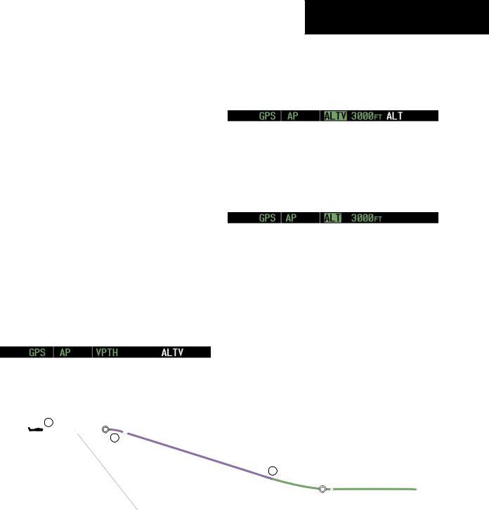
Vertical Path Tracking descent to VNAV Target Altitude:
1)Select VNAV flight control:
a)Using the ALT Knob, set the Selected Altitude below the VNAV Target Altitude of 3000 ft.
b)Press the VNV Key to arm Vertical Path Tracking Mode. The white annunciation‘VPTH’ appears.
Figure 6-34 FLC Descent
6-28 |
Garmin G1000 Cockpit Reference Guide for the Cessna Nav III |
SECTION 6 – AUTOMATIC
FLIGHT CONTROL
c)If Vertical Path Tracking Mode is armed more than five minutes prior to descent path capture, acknowledgment is required for the flight director to transition from Altitude Hold to Vertical Path Tracking Mode. To proceed with descent path capture if the white ‘VPTH’ annunciation begins flashing,
Press the VNV Key OR:
Turn the ALT Knob to adjust the Selected Altitude
If the descent is not confirmed by the time of interception, Vertical Path Tracking Mode remains armed and the descent is not captured.
2)When the top-of-descent (TOD) is reached, the flight director transitions toVertical PathTracking Mode and begins the descent to the VNAV Target Altitude. Intention to capture the VNAV Target Altitude is indicated by the white ‘ALTV’ annunciation.
3)As the aircraft nears theVNAVTargetAltitude,the flight director transitions toVNAVTargetAltitude Capture Mode, indicated by the green ‘ALTV’ annunciation flashing for up to ten seconds.
The green ‘ALT’ annunciation flashes for up to ten seconds upon reaching 50 ft from the VNAV Target Altitude; the autopilot transitions to Altitude Hold Mode and levels the aircraft at the vertical waypoint.
Non-path descents can be flown while under VNAV guidance using Pitch Hold, Vertical Speed, or Flight Level Change Mode. Flight Level Change Mode is used for this example.
Non-path descent:
1)Command a non-path descent using Flight Level Change Mode:
a)Using the ALT Knob, set the Selected Altitude below the current aircraft altitude to 5,000 ft.
���������
Figure 6-35 VPTH Descent
Garmin G1000 Cockpit Reference Guide for the Cessna Nav III |
6-29 |
SECTION 6 – AUTOMATIC
FLIGHT CONTROL
b)Press the FLC Key before the planned TOD during a vertical profile level leg (tracked using Altitude Hold Mode). The Airspeed Reference defaults to the current aircraft airspeed. Vertical Path Tracking and Selected Altitude Capture Mode is armed automatically.
2)Reduce power to allow descent in Flight Level Change Mode. The autopilot maintains the Airspeed Reference.
3)As the aircraft nears the Selected Altitude, the flight director transitions to Selected Altitude Capture Mode, indicated by the green ‘ALTS’ annunciation flashing for up to ten seconds.
The green‘ALT’ annunciation flashes for up to ten seconds upon reaching 50 ft from the Selected Altitude;the autopilot transitions toAltitude Hold Mode and levels the aircraft.
4)WhenthenextTODisreached,VerticalPathTracking becomes active (may require acknowledgment to allow descent path capture).
5)As the aircraft nears theVNAVTargetAltitude,the flight director transitions toVNAVTargetAltitude Capture Mode, indicated by the green ‘ALTV’ annunciation flashing for up to ten seconds.
The green ‘ALT’ annunciation flashes for up to ten seconds upon reaching 50 ft from the VNAV Target Altitude; the autopilot transitions to Altitude Hold Mode and levels the aircraft at the vertical waypoint.
|
|
|
|
|
|
|
|
|
|
|
|
|
|
|
|
|
|
|
|
|
||
|
|
||
|
|
|
|
|
|
|
Figure 6-36 Non-path Descent
6-30 |
Garmin G1000 Cockpit Reference Guide for the Cessna Nav III |
Approach
Flying an ILS approach:
1)Transition from GPS Navigation Mode to Heading Select Mode.
a)Load the Runway 29R ILS approach for KFAT into the flight plan.
b)Select ‘VECTORS’ for the transition.
c)Use the HDG Knob to set the Selected Heading after getting vectors from ATC.
d)Press the HDG Key. The autopilot turns the aircraft to the desired heading.
|
|
33 |
0 |
|
|
30 |
3 |
|
|
7 |
6 |
|
|
2 |
|
1 |
GPS |
Course |
9 |
|
|
||
|
|
|
SECTION 6 – AUTOMATIC
FLIGHT CONTROL
2)Use Heading Select Mode to comply with ATC vectors as requested.
3)Tune the localizer frequency.
4)Press the APR Key when cleared for approach to arm Approach and Glideslope modes. ‘LOC’ and ‘GS’ appear in white as armed mode annunciations.
The navigation source on the HSI automatically switches to LOC. After this switch occurs, the localizer signal can be captured and the autopilot and flight director determine when to begin the turn to intercept the final approach course.
5)There are two options available at this point, as the autopilot flies the ILS approach:
•Push the AP DISC Switch at the Decision Height and land the aircraft.
•Use the GA Switch to execute a missed approach.
|
VMode |
GPS |
NA |
12
81 |
51 |
122 |
291 |
|
KFAT |
||
|
HDG |
|
|
Mode |
|
|
LOC |
APR/ |
|
GS |
|
|
|
Mode |
2 |
3 |
Figure 6-37 ILS Approach to KFAT |
5 |
025 |
|
|
SANGO |
|
4 |
111 |
|
075 |
Garmin G1000 Cockpit Reference Guide for the Cessna Nav III |
6-31 |
SECTION 6 – AUTOMATIC
FLIGHT CONTROL
NOTE: Support for WAAS precision approaches is available only in installations with GIA 63W Integrated Avionics Units and when WAAS is available.
Flying a WAAS precision approach:
1)Arm flight director modes for a precision approach:
a)Make sure GPS is the selected navigation source (use CDI Softkey to change navigation source).
b)Load the Runway 29R LPV approach for KFAT into the flight plan.
33 |
0 |
30 |
3 |
7 2
2)Press the APR Key once clearance for approach has been acquired. GPS Approach Mode is activated (provided the crosstrack error is less than 2 nm) and Glidepath Mode is armed.
3)Once the glidepath is captured, Glidepath Mode becomes active.
4)There are two options available at this point, as the autopilot flies the approach:
•Push the AP DISC Switch at the Decision Height and land the aircraft.
•Use the GA Switch to execute a missed
approach.
6
GPS |
APR/ |
|
GP |
|
|
|
Mode |
2
Figure 6-38 LPV Approach to KFAT
6-32 |
Garmin G1000 Cockpit Reference Guide for the Cessna Nav III |