

Shema_EC7
.pdfContent |
1 |
|
13.1 |
Circuit Diagram Description ................................................................................................ |
2 |
13.2 |
Icon Symbols ...................................................................................................................... |
6 |
13.3 |
Fuse and Relay .................................................................................................................... |
8 |
13.4 |
Layout of Harness and the Connector ................................................................................ |
24 |
13.5 |
Layout of Grounding Points ................................................................................................ |
97 |
13.6 |
Circuit Diagram................................................................................................................. |
112 |
13.7 Abbreviation...................................................................................................................... |
346 |
|
EC718/EC718-RV EC715/EC715RV |
2010 |

2 |
Circuit Diagram Description |
|
|
|
|
|
Front wiper |
|
|
|
|
Indoor fuse
Relay box
To washer pump
Front wiper motor
Intermittent
control
Washing switch
Front wiper switch
Wiper washer switch
2010 |
EC718/EC718-RV EC715/EC715RV |

3
Indoor fuse relay |
|
Indoor fuse relay box |
box |
|
|
|
|
|
Rear washer motor
Wiper washer switch
Rear wiper switch
Rear wiper motor
EC718/EC718-RV EC715/EC715RV |
2010 |

4 |
13.2 Icon Symbols |
1.System name
2.Harness connector number;
The numbering rule of harness connectors in this electric circuit atlas is based on the harness, for example, the number of harness connector of water temperature sensor in engine harness is EN23, in which EN refers to harness code and 23 to connector series number.
The harnesses indicated by the codes are shown in following table:
Definition |
Harness name |
|
CA |
Engine compartment harness |
|
|
|
|
EN |
Engine harness (Delphi system) |
|
|
|
|
E0 |
Engine harness (Mitsubishi system) |
|
|
|
|
IP |
Instrument panel harness |
|
|
|
|
SO |
Base plate harness (LH), baggage compartment |
|
harness, base plate harness (RH) |
||
|
||
|
|
|
DR |
Door harness |
|
|
|
|
RF |
Interior light (ceiling) harness |
|
|
|
|
J |
Indoor fuse, relay box |
|
|
|
Note:
1.The definition of door harness includes four door harnesses.
2.The details of numbers of harness connectors refer to harness layout.
3.Component name.
4.Display the system information related to the electric
circuit connection.
5The connection between plugs shall be indicated with fine solid line and covered with grey shade so
as to differ from the physical harness. The physical harness shall be indicated with heavy solid line, of which the color is same to that of actual conductor.
6.Display the conductor color. The color codes are shown in following table:
Color code |
Conductor |
Illustration |
|
color |
|||
|
|
||
B |
Black |
|
|
Gr |
Grey |
|
|
Br |
Brown |
|
|
L |
Blue |
|
|
G |
Green |
|
|
R |
Red |
|
|
Y |
Yellow |
|
|
O |
Orange |
|
|
W |
White |
|
|
V |
Violet |
|
|
P |
Pink |
|
|
Lg |
Light green |
|
|
C |
Light blue |
|
If the conductor is of two color wire, the first letter indicates the base color of conductor and the second letter indicates the stripe color, and they are separated with “/”.
For example, the conductor marked as G/B refers to green base and black strip.
7.Display the terminal numbers of socket connectors note the terminal sequences of harness connectors which are connected are of mirror image, as shown in following figure:
8.Number of grounding point. Except the first letter of grounding point of engine harness is A, the other Harnesses are indicated with serial numbers with the first letter of G. The details of grounding point positions refer to grounding point layout.
9.Power type supplying the fuse
10.Conductor node.
Not-connected cross lines
Connected cross lines
11.The fuse number consists of fuse code and serial number. The codes of fuse in engine compartment are of EF and JF, and those of indoor fuse are of IF and SF. The fuse number details refer to fuse list.
12.The relay number is indicated with single English letter. The details refer to relay list.
2010 |
EC718/EC718-RV EC715/EC715RV |

5
13.If the electric circuit designs differ due to different vehicle model, engine type or configurations, indicate with dashed line in the circuit diagram and described besides the line.
|
|
|
L.R. |
R.R |
|
reversing |
|
revers |
lamp |
|
|
|
ing |
|
|
|
|
|
|
lamp |
|
|
Hatch |
|
|
back |
Sedan |
||
car |
|
car |
14If “8” shape mark is used between electric circuit lines, it indicate this circuit is of twisted pair wire which is mainly used for signal circuit of sensor or data communication circuit.
15.If the content of a system is so much that its circuit needs to be indicated in many pages. The start point of circuit is indicated with and the arrival point with. If more than one circuits continue in next page, they will be indicated with letters B, C and etc. and deduce in analogy.
EC718/EC718-RV EC715/EC715RV |
2010 |

6 |
13.2 Icon Symbols |
Grounding
Temperature
sensor
Clip jumper
Solenoid valve
Small load fuse
Medium load fuse
Large load fuse
Heater
Normal close relay
Normal open relay
Double throw relay
Resistor
Potentiometer
Variable resistor
Ignition coil
Knock sensor
Battery
Capacitor
Cigarette lighter
Antenna
Normal open switch
Normal close switch
Double throw switch
Ignition switch
2010 |
EC718/EC718-RV EC715/EC715RV |

7
Diode
Photo diode
Light emitting diode
Motor
Limit switch
Safety belt pre-tensioner
Solenoid valve
Bulb
Circuit direction
Horn
Clock spring
Airbag
Not-connected
cross lines
Twisted wire
Starter
Fan assembly
Oxygen sensor
Low speed fan relay B
Connected cross lines
EC718/EC718-RV EC715/EC715RV |
2010 |
8 |
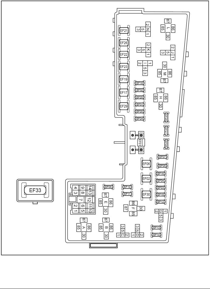
13.3.1 Engine compartment fuse, relay box |
13.3 Fuse, relay |
Engine Compartment Fuse, Relay Box
Terminal fuse for battery positive pole
2010 |
EC718/EC718-RV EC715/EC715RV |

9
Internal Circuit Diagram of Engine Compartment Fuse and Relay Box
EC718/EC718-RV EC715/EC715RV |
2010 |

10
Internal Circuit Diagram of Engine Compartment Fuse and Relay Box (continued 1)
2010 |
EC718/EC718-RV EC715/EC715RV |