

Environmental Biotechnology - Jordening and Winter
.pdf5.3 Reactor Design Parameters 151
with a separate acidification reactor) can be higher by a factor of 4–5 than that of reactors fed with complex substrates (Henze and Harremoes, 1983).
Inhibitory substances such as sulfur compounds may play a major role, as in yeast processing (Friedmann and Märkl, 1994). It is also essential that results concerning load refer to an average of a stable continuous process rather than to a singular maximum. Even results obtained in laboratory reactors differ in general from pilot-plant and full-scale reactors operating at the factory site with variations in substrate quality and concentrations and additional fluctuations.
5.3.3.1Solids in Stationary Fixed-film Reactors
Suspended solids and even suspended biomass can cause reactor clogging, which can be reinforced by extracellular polysaccharides secreted by acidogenic bacteria (Ehlinger et al., 1987). Therefore, backwash and excess sludge removal must be provided for in the reactor design. Gas-phase desorption and transport through the reactor must be possible. Fixed-bed systems are not feasible for wastewater having high solids content or components that tend to precipitate, such as calcium ions.
5.3.3.2Solids in Fluidized-bed Reactors
Solids from the wastewater can cause clogging, especially at the entrance region of the reactor. Holst et al. (1997) recommend solids concentrations <0.5 kg m–3 to prevent problems of clogging in the distribution system, but Mösche (1998) reported that even solid concentrations up to 1.7 kg m–3 did not cause problems. This difference can be explained by differences in the composition of the solids as well as in the construction of the reactor inlet.
Some inorganic compounds, such as calcium carbonate and ammonium magnesium phosphate, precipitate mainly onto the support in the reactor, when the actual concentrations are beyond the equilibrium. At higher concentrations of precipitated solids on the support, diffusion limitation occurs. In such situations it is necessary to enable removing this material and replacing it with uncovered new support. Sand and other materials with a high settling velocity in relation to the support must either be removed before entering the reactor or be removed by a device at the bottom of the reactor (as described under the first subheading in section 5.3.4.2).
5.3.4
Reactor Geometry and Technological Aspects
Some general aspects of reactor design are dealt with in Chapter 6 of this book.
5.3.4.1Fixed-bed Reactors
Upflow reactors tend to be favored, because they allow clumps of biomass to be retained in the filter by gravity, and the start-up period may be shorter (e.g., 3–4 months compared to 4–6 months for downflow reactors) (Andrews, 1988; Weiland et al., 1988). The height is limited by the gradients of the biomass and reaction rate.
152 5 High-rate Anaerobic Wastewater Treatment
Fixed-bed reactors do not require major specific design considerations. The ratio of height to diameter is usually in the range 1–2. The inlet must provide equal distribution of the wastewater by means of distribution devices, generally a system of tubes with nozzles, about one for each 5–10 m2 (Lettinga et al., 1983). The fluid flow should in general be about 1 m h–1, up to a maximum of 2 m h–1 (Austermann-Haun et al., 1993).
5.3.4.2 Fluidized-bed Reactors
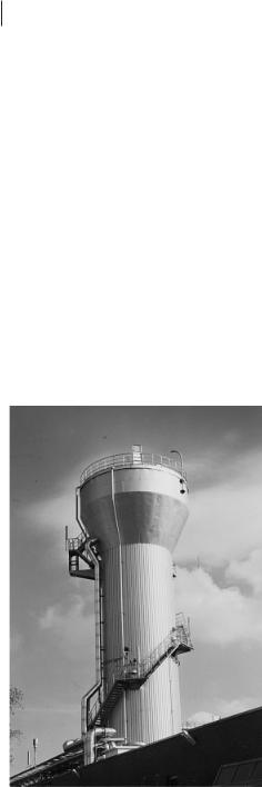
Fluidized-bed reactors are taller than agitated tanks or stationary-bed reactors. The height–diameter ratio for technical plants varies from 2 to 5. Figure 5.6 shows a technical plant with 500 m3 volume. The ratio of height to diameter should not be too high with respect to axial concentration gradients, which increase with the height of the reactor. But difficulties concerning uniform fluidization of the support increase with increasing reactor diameter (Couderc, 1985). Therefore, a compromise has to be found.
Whereas fluidized bed reactors are mostly cylindrical, the use of tapered fluidized be reactors has also been investigated and showed advantages concerning the performance (Huang et al., 2000)
Fig. 5.6 Technical-scale anaerobic fluid- ized-bed reactor (sugar factory in Clauen, Germany).

5.3 Reactor Design Parameters 153
Fluidization of the Support
One of the key factors for the development of a fluidized-bed system is the fluidization zone. This zone has to provide a homogenous distribution of support and substrate by the incoming feed to prevent any dead-zone formation and to avoid high shear forces. Most laboratory-scale reactors work with inlet tubes in the downward direction or sieves, sometimes also with glass beads for providing a uniform upflow distribution. These are not applicable to full-scale reactors. The use of a multitube system could be a solution for technical reactors, but such a system is expensive and may be subject to problems with solids (blocking) or precipitation (lime or other inorganic compounds) (Iza, 1991).
Problems in distribution systems are sometimes discussed in the literature (Franklin et al., 1992; Oliva et al., 1990), but new developments and improvements of existing distribution systems are rarely described in detail.
A fluidized-bed bottom used in a 500 m3 BMA (Braunschweiger Maschinenbauanstalt) reactor with sugar factory wastewater is shown in Figure 5.7 (Jördening et al., 1996). It has a conical shape with 12 concentric pipes for the incoming water. Due to an inner double cone, the superficial liquid velocity is twice that of the reaction zone. So only material with a high settling velocity can settle in this part. A valve at the lower end of the cone allows these particles to be removed.
Bed Height and Loss of Support
The fluidized bed’s height is determined by the flow rate and depends on the support. It varies over time with growth of the biofilm, the gas production rate and possible precipitates on the support. Changes occur only slightly with time.
Strategies for preventing support loss are different in several systems on the technical scale:
•For the Anitron process (sand as support) the bed height can be controlled by a stationary support/biomass-separating device at the maximum bed height, which contains the removal of support from the reactor by a centrifugal pump which dislodges the biomass from the support. While the support is fed back to the reactor,
Fig. 5.7 Flow distribution system for fluidized-bed reactors (Jördening et al., 1996).

154 5 High-rate Anaerobic Wastewater Treatment
excess biomass is discarded. The maximum bed height is at least 1.5 m below the overflow section.
•For the Gist-Brocades (sand as support) and the Anaflux processes (Biolite® as support) the bed height is controlled only by the fluidization velocity. Biocatalyst loss is prevented by means of three-phase separation constructions. Although the Gist-Brocades system does not contain a unit for removing support, the Anaflux and the Anitron systems are provided with a centrifugal pump for removal of excess biomass from the separator. Therefore, automatic control is not necessary, but daily control via a sample port is useful to prevent support loss.
5.4
Reactor Operation
5.4.1
Start-up Procedure
The start-up of fixed-bed reactors is governed by several parameters (Weiland et al., 1988; Burkhardt and Jördening, 1994):
•size and quality of the inoculum, notably the activity of slow-growing methanogens
•degree of adaptation, mainly the content of bacteria adapted to adhesion
•degree of biomass retention
The limited activity, and thus slow growth of propionic or lactic acid converting bacteria are of crucial importance, and the load must be controlled so as to maintain the substrates below growth-limiting concentrations. The initial load should be low, in the range of 0.1 kg(COD) kg–1(VSS) d–1 (Henze and Harremoes, 1983). Start-up is facilitated by Ca2+ ions in the concentration range 100–200 g m–3. The load may be increased at a rate of 5%–10% d–1. The overall time required from start-up to full load may be 1–3 months. It can be much less when an adapted inoculum and a sufficient amount of biomass are used. In industries working in campaign periods, restart after storage of the biomass (in the reactor at ambient temperature) is rather straightforward reaches full load within several days.
The time required for the development of a well-attached film on the support in fluidized beds is sometimes very long in contrast to that in suspended systems (Heijnen et al., 1986).
Because continuous inoculation seems to be impractical for technical systems, batch inoculation is usually used. This means that digester sludge is added and the continuous flow of wastewater to the reactor is started after several days or weeks of adaptation. If suspended bacteria are used as an inoculum, the start of the continuous work will cause a significant loss of activity. Hence, it is advantageous to use – whenever possible – immobilized inoculum from comparable plants to reduce the time for adaptation and the loss of inoculum. Jördening et al. (1991) reported that

5.4 Reactor Operation 155
the use of immobilized inoculum could reduce the start-up period by about 30%. Heijnen et al. (1986) showed, by comparing data in the literature, that the loading rate profile is an additional key factor affecting rapid biofilm development: the use of a so-called ‘maximum load profile’ reduces the start-up time up to a half that achieved with the so-called ‘maximum efficiency profile’. The ‘maximum load profile’ means that the load is increased if the concentration of volatile fatty acids in the reactor is high (>2000 ppm); the ‘maximum efficiency profile’ means that the load is increased only if the concentration of volatile fatty acids in the reactor is decreased to a minimum (<100 ppm) and therefore conversion to the extent possible has been achieved.
5.4.2
Operation Results: Stationary Bed
Several reviews have been published: e.g., by Henze and Harremoes (1983), Switzenbaum (1983) and Austermann-Haun et al. (1993). Table 5.3 shows selected data for typical substrates and carriers on the laboratory and pilot scale, which also seem appropriate for scale-up to the industrial level. One example is included representing very high load, however, with an expensive carrier (Siran®). Most typical loading rates (kg m–3 d–1 COD) are in the range 3–10 for common wastewater from agricultural and food processes with high conversion (over 80% of degradable COD), but
Table 5.3 Data from laboratoryand pilot-scale anaerobic stationary-bed systems.
Substrate |
CODin |
Carrier |
Load |
Conversion |
Reference |
|
(kg m–3) |
|
(kg m–3 d–1) |
(%) |
|
|
|
|
|
|
|
Sucrose 30%, |
< 3–6 |
modular blocks |
2–4 |
83–85 |
Young and Dahab (1983) |
ethanol 65% |
|
pall rings |
|
|
|
Distillery |
<10 |
Plasdek® |
|
|
Weiland and |
effluentsa |
|
Flocor® |
8–10 |
90–95 |
Wulfert (1986) |
|
|
Hiflow 90® |
|
|
|
Volatile acids |
< 6 |
|
1.7–3.4 |
87–98 |
Young and McCarty (1969)b |
Protein–carbohydrate |
|
|
3.1–3.3 |
90–50 |
Mueller and |
waste |
|
|
|
|
Mancini (1975)c |
Sludge heat- |
<10 |
|
6.5 |
55–65 |
Donovan (1981)c |
treatment liquor |
|
|
|
|
|
Chemical plant waste |
<16 |
|
|
65 |
Ragan (1981)c |
Sulfite evaporator |
<37 |
Siran® Raschig |
45 |
84 |
Ney et al. (1989) |
condensated |
|
rings |
|
|
|
a Acidification prior to methanogenesis. b Test in different reactors.
c Taken from Switzenbaum (1983).
d Sulfite evaporator condensate: acetic acid 425, methanol 75, furfural 28 m.

156 5 High-rate Anaerobic Wastewater Treatment
there are also examples of loading rates of about 20 and even 40 kg m–3 d–1 COD. However, these rather exceptional results may not be suitable for scale-up.
A considerable number of technical-scale systems with volumes of several 10 m3 to several 1000 m3 are in operation. The sites are smalland medium-sized agricultural installations, typically treating wastewater from poultry, pig, and cattle farms and distilleries; mediumand large-scale reactors in food industries such as sugar, potato, starch, and dairy processing, paper and pulp manufacturers, and the chemical industry. Some typical data are summarized in Table 5.4. Acidification often occurs in the wastewater stream prior to feeding it to the methane reactor even when this is not mentioned in detail; notably, for substrates that easily undergo microbial fermentation. For example, this occurs in sugar industry wastewater, containing sucrose as the main substrate, which is stored in lagoons before being fed to a methane reactor. More examples and data have been published by Austermann-Haun et al. (1993).
Overloading may be possible without inactivation of the biomass (if an appropriate pH – least 6 – is maintained), but conversion decreases according to the maximal
Table 5.4 Data from industrial-scale anaerobic stationary bed systems.
Wastewater |
Reactor |
Support Material |
Load |
Removal |
Reference |
|
Size |
|
|
|
|
|
(m3) |
|
(kg m–3 d–1) |
(%) |
|
|
|
|
|
|
|
Meat processing |
22a |
porous glass (Siran®) |
10–50 |
up to 80 |
Breitenbücher (1994) |
Dairy |
260 |
plastic rings (Biofar®) |
10 |
|
Weiland et al. (1988) |
Dairy |
362 |
plastics (Flocor® and |
10–12 |
70–80 |
Austermann-Haun |
|
|
cloisonyle) |
|
|
et al. (1993) |
Sugar |
b |
plastics |
b |
90 |
Camilleri (1988), |
|
|
||||
|
|
|
|
|
Henry and Varaldo |
|
|
|
|
|
(1988) |
Sugar |
1400 |
plastic rings (Flocor) |
13 |
|
Weiland et al. (1988) |
Potato processing |
660 |
pallrings (100 mm) |
3–6 |
|
Weiland et al. (1988) |
Starch |
4300c |
lava rock |
25 |
>70 |
Schraewer (1988) |
Soft drink |
85 |
modular plastic blocks |
4–6 |
90 |
Austermann-Haun |
production |
|
(Plasdek®) |
|
|
et al. (1993) |
Distillery |
13 000 |
modular plastic blocks |
8–12 |
|
Weiland et al. (1988) |
Distillery |
92 |
modular plastic blocks |
13 |
78 |
Austermann-Haun |
|
|
(BIO-NET®) |
|
|
et al. (1993) |
Chemical |
1900 |
plastics |
16–20 |
90 |
Henry and Varaldo |
industry |
|
|
|
|
(1988) |
a Two-stage system with acidification (40 m3) as the first stage. b Up to 2000 m3 d–1 wastewater with 16 t d–1 COD.
c Two-stage system with acidification reactor of 1000 m3 as the first stage.
5.5 Conclusions 157
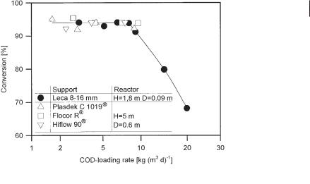
Fig. 5.8 Influence of volumetric loading rate and support material on reactor conversion (Weiland and Wulfert, 1986).
activity of biomass (in general 1–2 kg COD m–3 kg–1 dry biomass; Figure 5.8) (Weiland and Wulfert, 1986).
5.4.3
Operational Results: Fluidized-bed Reactors
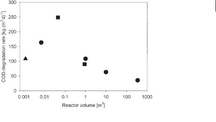
The performance of fluidized-bed reactors on the laboratory and pilot scale is sometimes excellent: Keim et al. (1989) used Siran® spheres in a fluidized-bed reactor for the treatment of evaporation condensate and reported a loading rate up to 315 kg m–3 d–1 with 79% removal. Jördening et al. (1991) used another sintered glass (Poraver®) to treat a sugar wastewater with loading rates up to 183 kg m–3 d–1 and achieved 89% removal. Data from some laboratoryand pilot-scale plants are given in Table 5.5.
Despite these results on the laboratory scale, the data reported for performance on the technical scale (Table 5.6) are in a significantly lower range: 15–50 kg m–3 d–1 (Fig. 5.9) (see e.g. Ehlinger, 1994; Franklin et al., 1992; Jördening, 1996; Jördening and Küster, 1997; Oliva et al., 1990).
5.5 Conclusions
As a general conclusion, we can state that both fixedand fluidized-bed reactors are well established on the industrial scale, notably in the food and related industries (e.g., breweries and distilleries) and in the paper and pulp industry, where the substrates are of natural origin, but also in other areas, e.g., the chemical industry.

158 |
|
5 High-rate Anaerobic Wastewater Treatment |
|
|
|
||||
|
|
|
|
||||||
Table 5.5 Data of laboratory and pilot-scale anaerobic fluidized bed systems. |
|
|
|||||||
|
|
|
|
|
|
|
|
|
|
Waste |
Support |
Reactor |
Ratioa |
Loading |
Concen- |
HRT |
Removal |
Reference |
|
|
|
|
Volume |
|
|
tration |
|
|
|
|
|
|
(m3) |
|
(kg m–3 d–1) |
(kg m–3) |
(h) |
(%) |
|
|
|
|
|
|
|
|
|
|
|
Spoiled beer |
sand |
64 × 10–3 |
18 |
1–14.8 |
1–12 |
0.2–7 |
75–87 |
Anderson et al. (1990) |
|
Synthetics |
GACb |
1.2 × 10⁻³ |
5.6 |
5.8–108 |
0.5–9 |
0.5–8 |
75–98 |
Chen et al. (1995) |
|
Synthetics |
sand |
70 × 10–3 |
20 |
3–20 |
13 |
1.5 |
98 |
Jördening (1987) |
|
Fruits and |
biolite |
|
25 |
38 |
|
|
>80 |
Menon et al. (1997) |
|
vegetables |
|
|
|
|
|
|
|
|
|
Brewery |
sand |
63 × 10–3 |
18.7 |
14.6 |
1–3.5 |
5–34 |
70b |
Ozturk et al. (1989) |
|
a Height/diameter.
b Granular activated carbon.
Table 5.6 Data from technical-scale anaerobic fluidized-bed systems.
Waste |
Company |
Support |
Reactor |
Ratioa |
Loading |
Concen- |
HRT |
Removal |
Reference |
|
|
|
Volume |
|
|
tration |
|
|
|
|
|
|
(m3) |
|
(kg m–3 d–1) |
(kg m–3) |
(h) |
(%) |
|
|
|
|
|
|
|
|
|
|
|
Soybeans |
Dorr–Oliver |
sand |
304 |
2.0 |
14–21 |
0.8–10 |
|
75–80 |
Sutton |
|
|
|
|
|
|
|
|
|
et al. (1982) |
Several |
Degremont |
biolite |
210–480 |
|
16–21 |
3.8–5 |
0.25 |
50–60 |
Ehlinger |
|
|
|
|
|
|
|
|
|
(1994) |
Yeast and |
Gist- |
sand |
400 |
4.4 |
8–30 |
1.9–4 |
0.14– |
95–98 |
Franklin |
pharma- |
Brocades |
|
|
|
|
|
0.41 |
|
et al. (1992) |
ceuticals |
|
|
|
|
|
|
|
|
|
Evapora- |
Gist- |
granules |
125 |
|
21–35 |
5–22.5 |
|
|
Franklin |
tion con- |
Brocades |
|
|
|
|
|
|
|
et al. (1992) |
densates |
|
|
|
|
|
|
|
|
|
and osmotic |
|
|
|
|
|
|
|
|
|
permeates |
|
|
|
|
|
|
|
|
|
Sugarbeets |
BMA |
pumice |
500 |
5.0 |
20–60 |
1–5 |
1.5 |
65–78 |
Jördening |
|
|
|
|
|
|
|
|
|
(1996) |
Brewery |
Degrement |
biolite |
165 |
3.2 |
|
|
|
|
Oliva |
|
|
|
|
|
|
|
|
|
et al. (1990) |
a Height/diameter.
Specific limitations, however, must be taken into consideration:
•Acidification inside the methane reactor requires a higher residence time than in two-stage systems with acidification as a first stage; this also provides safer and more stable processing, e.g., when a shock load occurs – a quite common situation in practice.
References 159
Fig. 5.9 Changes in reactor performance as a function of reactor volume ( Keim et al. 1989, Burkhardt and Jördening 1994, Chen et al. 1995).
•Wastewater free of suspended solids is required for fixed-bed reactors. No precipitation of solids should occur inside the reactor.
•Advantages of both types of systems include higher density of biomass and, therefore, higher reaction rates and a considerably smaller reactor volume required than in conventional systems such as stirred tanks. This is especially true for fluid- ized-bed reactors, since they can provide a much larger support surface and, hence, a high biomass concentration per volume. Much less space is required due to the relatively small reactor volume and the high ratio of height to diameter of the reactors.
•For these reasons, investment costs are lower than for systems without biomass immobilization.
References
Anderson, G. K., Ozturk, I., Saw, C. B., Pilotscale experiences on anaerobic fluidized bed treatment of brewery wastes, Water Sci. Technol. 1990, 22, 157–166.
Andrews, G. F., Design of fixed film and fluidized bed bioreactors, in: Handbook on Anaerobic Fermentations (Erickson, L. E., Fung, Y.-C., eds.), pp. 765–802. New York 1988: Marcel Dekker.
Austermann-Haun, U., Kunst, S., Saake, M., Seyfried, C. F., Behandlung von Abwässern, in: Anaerobtechnik (Böhnke, B., Bischofsberger, W., Seyfried, C. F., eds.), pp. 467–696. Berlin 1993: SpringerVerlag.
Balaguer, M. D., Vicent, M. T., Paris, J. M., Anaerobic fluidized bed with sepiolite as support for anaerobic treatment of vinasse, Bio- technol. Lett. 1992, 5, 333–338.
Bird, R. B., Stewart, W. E., Lightfood, E. N.,
Transport Phenomena. New York 1960: Wiley. Breitenbücher, K., Hochleistung durch mehr Biomasse, UTA Umwelttechnik Aktuell 1994,
5, 372–374.
Burkhardt, C., Jördening, H.-J., Maßstabsvergrößerung und Betriebsdaten von anaeroben Hochleistungs-Fließbettreaktoren, in: Anaerobe Behandlung von festen und flüssigen Rückständen (Märkl, H., Stegmann, R., eds.), pp. 145–162. Weinheim 1994: VCH.

160 5 High-rate Anaerobic Wastewater Treatment
Camilleri, C., Start-up of fixed film stationary bed anaerobic reactors, in: Anaerobic Digestion 1988 (Hall, E. R., Hobson, P. N., eds.), pp. 407–412. Oxford 1988: Pergamon.
Carrondo, M. J. T., Silva, J. M. C., Figuera, M. I. I., Ghano, R. M. B., Oliveira, J. F. S., Anaerobic filter treatment of molasses fermentation wastewater, Water Sci. Technol. 1983, 15, 117–126.
Chen, S. J., Li, C. T., Shieh, W. K., Performance evaluation of the anaerobic fluidized bed system. I. Substrate utilization and gas production, J. Chem. Technol. Biotechnol.
1995, 35B, 101–109.
Couderc, J.-P., Incipient fluidization and particulate systems, in: Fluidization, 2nd edn. (Davidson, J. F., Clift, R., eds.), pp. 1–46. London 1985: Academic.
Demirel, B., Yenigün, O., Two-phase anaerobic digestion processes: a review, J. Chem Technol. Biotechnol 2002, 77, 743–755
Diaz-Baez, M. C., A study of factors affecting attachment in the start up and operation of anaerobic fluidized bed reactors, in: PosterPapers 5th Int. Conf. Anaerobic Digestions
(Tilche, A., Rozzi, A., eds.), pp. 105–108. Bologna 1988: Monduzzi Editore.
Donovan, E. J., Treatment of high strength wastes by an anaerobic filter, Proc. Semin.: Anaerobic Filters: An Energy Plus for Wastewater Treatment, pp. 179–187, Howey In The Hills, FL 1981. ANL/CSNV-TM-50, 9–10 January 1980.
Ehlinger, F., Anaerobic biological fluidized beds: operating experiences in France,
pp. 315– 323, Proc. 7th Int. Symp. Anaerobic Digestion, Cape Town, South Africa 1994, 23–27 January 1994.
Ehlinger, F., Audic, J. M., Verrier, D., Faup, G. M., The influence of the carbon source on microbial clogging in an anaerobic filter,
Water Sci. Technol. 1987, 19, 261–273. Franklin, R. J., Koevoets, W. A. A., van Gils,
W. M. A., van der Pas, A., Application of the biobed upflow fluidized bed process for anaerobic waste water treatment, Water Sci. Technol. 1992, 25, 373–382.
Friedmann, H., Märkl, H., Der Einfluß der Produktgase auf die mikrobiologische Methanbildung, gwf Wasser Abwasser 1994, 6, 302–311.
Gonzalez-Gil, G., Seghezzo, L., Lettinga, G., Kleerebezem, R., Kinetics and mass-trans- fer phenomena in anaerobic granular
sludge, Biotechnol. Bioeng. 2000, 73, 125– 134
Hall, E. R., Biomass retention and mixing characteristics in fixed-film and suspended growth anaerobic reactors, pp. 371–396, Proc. JAWPR Specialized Semin. Anaerobic Treatment Waste Water in Fixed Film Reactors, 16– 18 June 1982, Copenhagen, Denmark 1982.
Heijnen, J. J., US Patent 4560479 (1985). Heijnen, J. J., Mulder, A., Enger, W., Hoeks, F.
(1986), Review on the application of anaerobic fluidized bed reactors in waste water treatment, Proc. EWPCA Conf. Anaerobic Wastewater Treat. pp. 159–173.
Henry, M., Varaldo, C., Anaerobic digestion treatment of chemical industry wastewaters at the Cuise–Lamotte (Oise) plant of Société Française Hoechst 479, in: Anaerobic Digestion 1988 (Hall, E. R., Hobson, P. N., eds.), pp. 479–486. Oxford 1988: Pergamon.
Henze, M., Harremoes, P., Anaerobic treatment of wastewater in fixed film reactors: a literature review, Water Sci. Technol. 1983, 15, 1–101.
Hoehn, D. C., The Effects of Thickness on the Structure and Metabolism of Bacterial Films, Thesis, University of Missouri 1970.
Holst, T. C., Truc, A., Pujol, R., Anaerobic fluidized beds: ten years of industrial experience, Water Sci. Technol. 1997, 36, 415–422.
Horn, H., Hempel, D. C., Modellierung von Substratumsatz und Stofftransport in Biofilmsystemen, gwf Wasser/Abwasser 1996,
137, 293–299.
Huang, J.-S., Yan, J.-L., Wu, C.-S., Comparative bioparticle and hydrodynamic characteristics of conventional and tapered anaerobic fluidized bioreactors, J Chem. Technol. Biotechnol. 2000, 75, 269–278
Iza, J., Fluidized bed reactors for anaerobic wastewater treatment, Water Sci. Technol. 1991, 24, 109–132.
Jördening, H.-J., Untersuchungen an Hochleistungsreaktoren zum anaeroben Abbau von calciumhaltigen Abwässern, Thesis, Technical University of Braunschweig, Germany (1987).
Jördening, H.-J., Scaling-up and operation of anaerobic fluidized bed reactors, Zuckerindus- trie 1996, 121, 847–854.
Jördening, H.-J., Küster, W., Betriebserfahrungen mit einem anaeroben Fließbettreaktor zur Behandlung von Zuckerfabriksabwasser,
Zuckerindustrie 1997, 122, 934–936.