

Frantisek Svec - Capillary Electrochromatography
.pdf10 |
F. Svec |
ments to their well-established instrumentation for capillary electrophoresis. Smaller companies such as Microtech Scientific, Inc. (Sunnyvale, CA, USA) and Unimicro Technologies, Inc. (Pleasanton, CA, USA) have developed instruments that can be used for mHPLC, CE, CEC, and pressurized CEC. Although this type of equipment addresses some of the weaknesses of the adapted CE instrumentation, the current market still lacks a reliable instrument for CEC that enables gradient elution, electrical fields higher than 1 kV/cm, or that includes a column compartment with well-controlled heating and accommodates even short capillaries. Current instrumentation is also not compatible with 96 or 384 well plate formats for direct sampling [40].
Since the commercial instrumentation does not satisfy the needs of specific CEC research,a number of groups described their home-built equipment. For example, Dittmann et al. developed an additional module that, once attached to HP
Fig. 6. Schematic of the solvent gradient elution CEC apparatus with ramping voltage accessory. (Reprinted with permission from [204] Copyright 1996 American Chemical Society)
Capillary Electrochromatography: a Rapidly Emerging Separation Method |
11 |
3DCE instrument, allows operation in a gradient mode [41]. Horváth’s group developed equipment for gradient CEC shown in Fig. 5 that allowed for combination of several chromatographic modes. These two and some other groups used a standard gradient HPLC system for the preparation of a mobile phase gradient that is delivered to the inlet of the capillary column through an interface. In contrast, Zare’s group used electroosmotic pumping from two eluent reservoirs (Fig. 6). The gradient was obtained by ramping the voltage between these two reservoirs.A detailed description of CEC instrumentation has been published recently by Steiner and Scherer [39].
4
Column Technologies for CEC
CEC is often inappropriately presented as a hybrid method that combines the capillary column format and electroosmotic flow employed in high-performance capillary electrophoresis with the use of a solid stationary phase and a separation mechanism, based on specific interactions of solutes with the stationary phase,characteristic of HPLC. Therefore CEC is most commonly implemented by means typical of both HPLC (packed columns) and CE (use of electrophoretic instrumentation). To date, both columns and instrumentation developed specifically for CEC remain scarce.
Although numerous groups around the world prepare CEC columns using a variety of approaches, the vast majority of these efforts mimic in one way or another standard HPLC column technology. However, aspects of this technology have proven difficult to implement on the capillary scale. Additionally, the stationary phases packed in CEC capillaries are often standard commercial HPLCgrade beads. Since these media are tailored for regular HPLC modes and their surface chemistries are optimized accordingly, their use incorrectly treats CEC as a subset of HPLC. Truly optimized, CEC packings should play a dual role: in addition to providing sites for the required interactions as in HPLC, they must also be involved in electroosmotic flow. As a result, packings that are excellent for HPLC may offer limited performance in the CEC mode. This realization of the basic differences between HPLC and CEC [33] has stimulated the development of both specific particulate packings having properties tuned for the needs of CEC as well as alternative column technologies. Generally,column technology remains currently one of the“hottest”issues in CEC and the progress in this area has been summarized in several recent review articles [42–46].
4.1
Packed Columns
The influence of HPLC on the development of separation media for CEC is rather obvious. For example, HPLC-like “hardware”, such as frits and packed columns, are employed.A number of various packing technologies have been reported that enable packing particles into narrow bore capillary columns. The solvent slurry packing appears to be the most popular technique that has been transferred di-

12 |
F. Svec |
Step 1)
Step 2)
Step 3)
Step 4)
Step 5)
Step 6)
Step 7)
Fig. 7. Scheme of a typical process used for packing CEC columns with beads
rectly from the HPLC. In contrast to relatively simple procedures widely used in HPLC, slurry packing of columns for CEC is more complex. The scheme in Fig. 7 shows as an example the individual steps required to fabricate an efficient column [47]. These include:
1.Attaching an in-line end-frit and packing the column by pumping a slurry of beads and solvent into the capillary under high pressure. Sonication is recommended to achieve better quality.
2.Flushing the packed column with water at high pressure to replace the solvent.
3.Preparing the outlet end-frit at the desired distance from the column end by sintering the silica beads using heating to a temperature of over 550 °C.
4.Removing the in-line end-frit and flushing out the extra-column packing materials using reversed flow direction.
5.Sintering of the packing materials to create the inlet end-frit at a distance representing the desired packed segment length followed by the removal of the polyimide coating from the detection window close to the outlet frit.
6.Cutting off the excess capillary close to the inlet frit.
7.Washing the packed capillary with the desired mobile phase
Since the general concept in CEC is to use packing materials with a beads size as small as possible, the viscosity of the liquid used for slurring the beads is critical. Equation (2) rearranged to
DP=u f h L/dp2 |
(3) |

Capillary Electrochromatography: a Rapidly Emerging Separation Method |
13 |
Table 4. Retention factors k¢ and column efficiencies N for an unretained thiourea and retained compound amylbenzene in columns packed by different methods [53]
Packing method |
Analyte |
k¢ |
N, plates/m |
|
|
|
|
Pressurized slurry |
Thiourea |
– |
86,600 |
|
Amylbenzene |
2.4 |
104,100 |
Supercritical CO2 |
Thiourea |
– |
143,200 |
|
Amylbenzene |
2.1 |
179,400 |
Centripetal force |
Thiourea |
– |
181,800 |
|
Amylbenzene |
2.2 |
181,800 |
Electrokinetic |
Thiourea |
– |
98,800 |
|
Amylbenzene |
2.3 |
136,700 |
|
|
|
|
clearly shows that the pressure required to push a liquid through the packed capillary exponentially increases with the decrease in bead diameter. Although use of slower flow velocity could be the solution to this problem, it would lead to excessively long packing times and the uncontrolled sedimentation of particles would reduce the homogeneity of the bed,thus negatively affecting the efficiency. Therefore, the use of liquids with lower viscosity is more convenient and enables packing columns at reasonable pressures. Several groups have reported the use of supercritical CO2 , a liquid that has very low viscosity and is easy to handle, in slurry packing of CEC columns [48, 49].
Yan developed a method that employs electrokinetic migration of charged silica beads [50]. The capillary is attached to a reservoir filled with slurry and the electric field is applied. The beads then move towards the anode in a stagnant liquid phase thus substituting the typical pumping of a liquid through the capillary. This remarkably simple method requires beads of very narrow size distribution since their surface area and consequently their net charge and migration rate increase with the decreasing bead diameter. If a polydisperse mixture of particles is used, the smaller beads migrate faster and this leads to the formation of inhomogeneous beds.
Colón and Maloney demonstrated another packing method that also avoids pumping the slurry through the column [51]. They used centripetal force to drive beads, which have a higher density than the liquid contained in solvent slurry, through the capillary. Their packing equipment enables a rotation speed of up to 3000 rpm at which the packing time is only 5–15 min.
Since the packing process always includes several steps, it requires specific skills to prepare highly efficient capillaries reproducibly. Obviously, the procedures described above are not trivial and the results obtained with each of them may differ substantially [52]. Table 4 compares data obtained for capillaries packed using four different methods [53]. The major challenge appears to be the in situ fabrication of retention frits. Tapered ends of the capillary columns introduced recently may help to solve this serious problem [54, 55]. The other problem is rearrangement of beads in the bed affected by their electromigration.
14 |
F. Svec |
4.1.1
Packing Materials
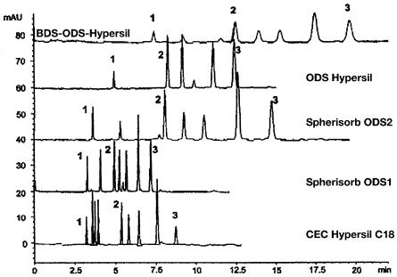
The correct choice of the packing material, typically functionalized silica beads, is extremely important to achieve the best performance in CEC. Since specialized CEC packings are emerging only slowly [7], typical HPLC separation media are being frequently used to pack CEC columns. Figure 8 demonstrates the effect of the stationary phase in the separation of polyaromatic hydrocarbons (PAHs) [56]. The results are simple to interpret: the base deactivated BDS-ODS-Hyper- sil contains the lowest surface coverage with silanol groups that are the driving force for flow. Therefore, the separation requires a long time. The magnitude of electroosmotic flow produced by the packings largely depends on the extent of endcapping of residual silanol groups that is required to avoid peak tailing in HPLC. In contrast,the specifically developed CEC Hypersil C18 affords both good flow and fair selectivity. Table 5 summarizes properties and electroosmotic mobilities for a selected group of commercial packings [57].
In order to increase the electroosmotic flow, a number of studies used beads with specifically designed surface chemistries that involved strong ion-exchange functionalities. The famous yet irreproducible separations of basic compounds with an efficiency of several millions of plates has been achieved with silica based
Fig. 8. Separation of polyaromatic hydrocarbons using commercial stationary phases. (Reprinted with permission from [56]. Copyright 1997 VCH-Wiley). Conditions: voltage 20 kV,capillary column 100 µm i.d., total length 33.5 cm, active length 25 cm, isocratic separation using 80:20 acetonitrile-50 mmol/l TRIS buffer pH=8. Peaks thiourea (1), naphthalene (2), and fluoranthrene (3)

Capillary Electrochromatography: a Rapidly Emerging Separation Method |
15 |
|
||||
|
Table 5. Properties of commercial stationary phases used in CEC [53] |
|
|
|||
|
|
|
|
|
|
|
|
Stationary phase |
End-capping |
Carbon content |
Surface areaa |
µEOb |
|
|
|
|
% |
m2/g |
104 · cm2 V–1 s–1 |
|
|
Nucleosil 5 C18 |
Fully capped |
13.6 |
350 |
1.56 |
|
|
LiChrospher RP-18 |
Uncapped |
21.7 |
450 |
1.45 |
|
|
Spherisorb Diol |
Uncapped |
1.9 |
220 |
0.80 |
|
|
Spherisorb S5 ODS2 |
Fully capped |
14.5 |
350 |
0.68 |
|
|
Zorbax BD-ODS |
Fully capped |
10.8 |
220 |
0.50 |
|
|
Hypersil ODS |
Fully capped |
11.0 |
170 |
0.14 |
|
|
Partisil 5 ODS3 |
Fully capped |
10.9 |
350 |
<0.01 |
|
|
Purospher RP-18 |
Chem. treated |
17.8 |
500 |
<0.01 |
|
a Values published by manufacturers. b Electroosmotic mobility.
strong cation exchanger [58]. El Rassi and Zhang developed“layered”chemistries with sulfonic acid ion exchange functionalities attached to the silica surface forming a sub-layer covered with a top layer of C18 alkyl chains [59, 60]. These materials afford much higher electroosmotic flow than their non-sulfonated counterparts and exhibit an interesting selectivity in the separation of nucleosides and other families of compounds.
The majority of CEC-studies in the early 1990s have been carried out with columns packed with the then state-of-the-art 5-mm octadecyl silica (ODS) beads [15, 61, 62]. Later in the decade, 3-µm beads became the HPLC industry standard and found their way rapidly to CEC. Their use enabled easy separation of hydrocarbons in the CEC mode with an efficiency of up to 400,000 plates/m [48,58]. Even better results were obtained with experimental particles having a diameter of 1.5 mm [63–67]. Unger’s group prepared and used even smaller beads with diameters in the submicrometer range [35, 68, 69]. Indeed, they achieved a further increase in efficiency to over 650,000 plates/m at a flow velocity of 3 mm/s. However, this was three time less than the value predicted by theory. This was explained by the effect of axial diffusion that does not depend on the particle size and becomes the dominating contribution to the peak broadening under these conditions, especially at the typical flow rates. Since an increase in the flow velocity of the magnitude required to minimize the effect of axial diffusion is difficult to achieve with the current instrumentation, the submicron sized packings do not offer any considerable advantage over the more common somewhat larger beads that are also easier to pack.
The effect of pore size on CEC separation was also studied in detail [70–75]. Figure 9 shows the van Deemter plots for a series of 7-µm ODS particles with pore size ranging from 10 to 400 nm. The best efficiency achieved with the large pore packing led to a conclusion that intraparticle flow contributes to the mass transfer in a way similar to that of perfusion chromatography and considerably improves column efficiency. The effect of pore size is also involved in the CEC separations of synthetic polymers in size-exclusion mode [76].

16 |
F. Svec |
22
100 Å
500 Å
20
300 Å
18
1000 Å
16
14
12
4000 Å
10
8
0 |
0.5 |
1 |
1.5 |
2 |
2.5 |
3 |
3.5 |
4 |
Fig. 9. Effect of pore size on the efficiency of CEC columns. (Reprinted with permission from [70]. Copyright 1997 VCH-Wiley). Conditions: field strength 100–500 V/cm, capillary column 75 mm i.d.,total length 30 cm,active length 25 cm,isocratic separation using 20:80 acetonitrile100 mmol/l phosphate buffer pH=6.9, marker acetone
4.2
Open-Tubular Geometry
In order to avoid tedious procedures required to prepare packed CEC columns, some groups are studying the use of empty capillaries. Since solute-stationary phase interactions are key to the CEC process, appropriate moieties must be bound to the capillary wall. However, the wall surface available for reaction is severely limited. For example, a 100 µm i.d. capillary only has a surface area of 3¥10–4 m2 per meter of length, with a density of functional sites of approximately 3.1¥1018 sites/m2, which equals 0.5 mmol sites/m2. Moreover, surface modification cannot involve all of the accessible silanol groups, since some must remain to support the EOF.As a result, the use of bare capillaries in CEC has been less successful.
In contrast, chemical etching of the inner wall of the fused-silica capillaries was used to increase the surface area. This enables achievement of a higher phase ratio since more alkyl functionalities can be attached to the surface, thus improving both the separation process and loadability of the column. The surface morphology of the etched capillary depends on the time the methanol solution of ammonium hydrogen difluoride is left in contact with the capillary and temperature at which the reaction is carried out (Fig. 10) [77]. The surface features have been described by Pesek to range “from spikes of silica material extending

Capillary Electrochromatography: a Rapidly Emerging Separation Method |
17 |
Fig. 10. Reaction path to etched and surface modified fused silica capillaries (modified from [78])

18 |
F. Svec |
Scanning Electron Micrographs of Etched Capillary Surfaces
A B
C
Fig. 11 A – C. Scanning electron micrographs of fused silica capillary surfaces etched with methanolic ammonium hydrogen difluoride solution. (Reprinted with permission from [78]. Copyright 2000 Elsevier). Etching process was carried out for: A 3 h at 300 °C; B, 2 h at 300 °C and 2 h at 400°C; C 2 h at 300°C and 1 h at 400°C
3–5 mm from the surface (Fig. 11A), to a series of hills or sand dunes (Fig. 11B), to large uniform boulder-like pieces of silica on the surface (Fig. 11C)”[78]. Each of these structures easily survives conditions typical of the CEC separations. This group also used their silanization/hydrosilation process to attach the alkyl moieties shown in Fig. 10. First, the surface is treated with a triethoxysilane to afford hydride functionalities. The desired alkyl is then attached by a catalyzed hy-

Capillary Electrochromatography: a Rapidly Emerging Separation Method |
19 |
|
|
|
|
|
|
|
|
|
|
Fig. 12 A– D. Separation of a mixture of cyctochromes C from various sources in 20 mm i.d. capillary columns. (Reprinted with permission from [78]. Copyright 2000 Elsevier). Conditions: A bare capillary; B unetched C18 modified capillary; C,D etched C18 modified capillary, total column length 50 cm, active length 25 cm, voltage 30 kV (A,B,C) and 15 kV (D), mobile phase 60 mmol/l a-alanine and 60 mmol/l lactic acid pH 3.7, detection at 211 nm, pressurized injection for 2 s using vacuum
drosilylation reaction. The bonded phase was characterized using a number of analytical methods such as diffuse reflectance infrared Fourier transform (DRIFT), solid-state cross-polarization magic-angle spinning (CP-MAS) NMR, photoelectron spectroscopy (ESCA) and optical methods such as UV-visible and fluorescence spectroscopy. Figure 12 demonstrates the significant effect of the surface treatment on the CEC separation of very similar proteins [79].