

Frantisek Svec - Capillary Electrochromatography
.pdfContinuous Annular Chromatography |
235 |
1 Introduction
Continuous annular chromatography is the only chromatography-based technology, which allows the continuous separation of a multicomponent mixture. Other than in SMB (Simulated Moving Bed) [1] based purifications where only two fractions – raffinate and extract – can be separated per unit, continuous annular chromatography allows the recovery of more than two fractions (up to five different peaks could be resolved [2]). Furthermore all commonly used chromatographic techniques like step-elution, gradient-elution and even displace- ment-elution can be performed continuously on a continuous annular chromatograph.With the CAC technology it becomes for the first time possible to run an Ion-Exchange purification continuously.
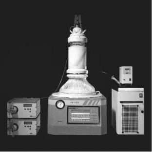
Figure 1 shows a schematic drawing of a CAC apparatus. The apparatus consists of two concentric cylinders standing one inside the other, forming an annulus into which the stationary phase is packed. This annular bed is slowly rotating about its vertical axis. Under isocratic elution conditions the feed mixture to be separated is introduced continuously at the top of the bed at a space that remains fixed in space while the rest of the annulus is flooded with elution buffer. As time progresses, helical component bands develop from the feed point, with
wash buffer inlet
continuous
load stream
stationary
 inlet distributor
eluent
flow
rotation of the column
separated compounds
Fig. 1. Principle of a continuous annular chromatograph
236 |
J. Wolfgang |
slopes dependent upon elution velocity, rotational speed, and the distribution coefficient of the component between the fluid and adsorbent phase.At steady state the component bands form regular helices between the feed sector at the top of the bed and the individual fixed exit points at the bottom of the annular bed, where the separated components can be continuously recovered.As long as conditions remain constant, the angular displacement of each component band from the feed point will also remain constant.
Under non-isocratic conditions as in ion exchange chromatography, any portion of the annular bed which is not receiving feed at a given time is either receiving wash buffer, step elution buffer(s), regeneration buffer, or equilibration buffer. Currently the P-CAC units allow the usage of up to seven different feed and buffer solutions. Thus, the P-CAC is a truly continuous, steady-state process, which retains the very attractive characteristics of being able to assure effective multicomponent separations with a flexibility typical for chromatography in general.
Giddings was the first to demonstrate that theoretically the rotating annular column can be superior to a fixed column of the same volume for process scale applications [3]. He recognized that many industrial scale packed columns exhibit non-uniformities in flow at large diameters, resulting in an increased plate height and loss of resolution. By using a rotating column with the same total cross-sectional area and bed height as a fixed column, but with an annulus size small enough so that flow non-uniformities do not occur, a process can be scaled up without loss of resolution. In other words, all things being equal, the geometry of a rotating bed with a small width annulus will have a larger number of plates, resulting in better resolution. He also pointed out that process control might be easier in continuous operation because it results from the column geometry, and not from careful timing of feed injection and product withdrawal as in a simulated continuous operation. Due to its truly continuous character the CAC technology features a very high throughput compared to traditional batch chromatographic separations.
2
General Overview
2.1
Brief Historical Survey
The idea of annular chromatography was first mentioned by A.J.P. Martin [4] in 1949 where he summarized a discussion with his colleagues Prof. Tiselius and Dr. Synge. In his summary Martin writes:
“An idea rising from a discussion with Prof. Tiselius and Dr. Synge during this discussion can also enable chromatography to be a continuous process, provided that the developing solvent returns the adsorbent to its initial state within a reasonable period. Imaging the chromatogram to be packed within a narrow annular space between two concentric cylinders. The upper surface of the chromatogram is flooded with solvent and at one point the solution to be separated
Continuous Annular Chromatography |
237 |
is fed on slowly. The annular chromatogram is slowly and uniformly rotated with the result that different zones will form helices of characteristic angle which can be collected at various fixed points around the bottom of the chromatogram”.
Martin further mentioned that the scheme he described has already been tried out by Dr. Wadman of the University of Bristol. Wadman, however, never published any results of his very first work on annular chromatography. Martin and Synge won a joint Nobel price in chemistry for their work in partition chromatography, Tiselius won a Nobel price in chemistry for his work in electrophoreses.
Between the time annular chromatography was first mentioned and the time when the first practical work was published, several years passed by. Between 1970 and 1990 most of the work on annular chromatography was performed at Oak Ridge National Laboratories (ORNL, Oak Ridge TN, USA).As we can find in the literature, most of the work done at ORNL focused on separation of metals [5–9], purification of sugars [10, 11] and the purification of standard model proteins such as hemoglobin, Bovine Serum Albumin [12] and amino acids [13]. In the 1990s some publications on annular chromatography from a Japanese group can be found. The work performed there mainly concentrates on the non-iso- cratic elution of proteins and amino acids [14–19].
2.2
Current Research and Development Status
In 1994 the work on annular chromatography at the Oak Ridge National Laboratory (ORNL) ended. The Japanese group mentioned above has not published anything related to annular chromatography since 1997. In 1994 Prior Technology GmbH (Götzis Austria), which was already in contact with C. Byers from the ORNL, started to use the annular chromatography technology to develop a system for the continuous separation of the precious metals rhodium, palladium, platinum, and iridium [2]. These studies carried out as Ph.D. work were performed in close cooperation between Prior Technology GmbH and the University of Technology of Graz, Austria, the Technion in Haifa Israel, and the Oak Ridge National Laboratories.
During the first four years (1994–1998) several papers were published by that group describing the separation of fructose, mannitol, and sorbitol [20, 21], the desalting of BSA [22],the recovery of a rhodium-based homogeneous catalyst [23], the separation of a steroid mixture [24], and the simultaneous separation of platinum group metals and iron [25]. Recently a study on the removal of ashes from a lactose concentrate was performed [26]. All work mentioned here was done on an annular chromatograph STD-100 E which was at that time sold by IsoPro Int. (Knoxville, TN, USA). In 1996 engineers at Prior Technology GmbH started to redesign and develop a new annular chromatograph; see Fig. 2.
In 1999 a new type of annular chromatograph was presented by Prior Separation Technology GmbH, a spin-off company of Prior Technology GmbH.At the same time the selling of the machine under the brand name of P-CAC started.
238 |
J. Wolfgang |
The most important changes in the design compared to the previous system include the usage of only FDA approved materials such as pharmagrade stainless steel or polyetheretherketone – PEEK and the implementation of glide ring sealings as interface between the rotating and the stationary parts of the column. Other changes concern the possibility to use the inner cylinder of the annular column as a heat exchanger, thus allowing a precise temperature control of the separation column. In 2000 Prior Separation Technology added a UV detector to the P-CAC system, allowing UV active substances to be monitored as they exit the annular column. Currently wavelengths of 280 nm and 260 nm can be used for the detection. As can be seen in Fig. 2 the P-CAC system itself currently consists of the annular column and the drive as well as a series of peripheral equipment such as pumps and a thermostat.
Using the new P-CAC systems basic research is currently performed at four different academic institutions. The first group at the center of Biotechnology of the Swiss Federal Institute of Technology in Lausanne, Switzerland, studies the usage of the P-CAC for the isolation of biologically active substances such as IgG [27] using affinity chromatography with r-Protein A Sepharose (Amersham Pharmacia Biotech, Uppsala Sweden) as the stationary phase as well as the continuous purification of plasmid DNA. The second group at the Institute of Applied Microbiology at the University of Agricultural Sciences in Vienna, Austria, studies the usage of the P-CAC for the separation and isolation of biomolecules in general [28, 29]. This group also examines the usage
Fig. 2. Picture of a commercially available P-CAC system from Prior Separation Technology GmbH
Continuous Annular Chromatography |
239 |
of two different stationary phases in one P-CAC column (ion-exchange resin on top of a size-exclusion resin) for the recovery of green fluorescent protein [29].
The third group at the department of Chemical Engineering at the University of Kaiserslautern, Germany uses the P-CAC as a chromatographic reactor. In this case chemical reactions coupled to the concomitant separation of the reactants in the P-CAC are studied. For these investigations the upper part of the annular column is used as the reaction zone, while the lower part of the column separates the products as well as the reactants.With the P-CAC as a continuous chromatographic reactor it is possible to shift the chemical equilibrium to the product side due to the fact that the products are always removed from the chemical reaction in the separation zone.As a second focal point the group in Kaiserslautern studies the heat transfer in a scaled-up P-CAC version. The fourth group at the department of Process Engineering at the Swiss Federal Institute of Technology in Zurich, Switzerland also uses the P-CAC as a chromatographic reactor and studies the esterification of glycerol and the recovery of the three different glycerides. This group started their work only in November 2000, and therefore no reference can be found on these studies.
Another group independently published the continuous purification of porcine lipase on a size-exclusion resin in an annular chromatograph [30]. The annular chromatograph used in this study was designed and fabricated at the department of Chemical Engineering at the University of New Hampshire (Durham). In 2001 studies on the refolding of recombinant proteins on a P-CAC will be started at the department of Chemical Engineering at the University of Cambridge, United Kingdom. In addition this group will also start to investigate the separation of peptides according to their chain-length.
3
Technical Description of the P-CAC System
Compared to the continuous annular chromatography systems sold by Isopro International and used throughout the ORNL studies, the P-CAC units developed by Prior Separation Technology feature several design modifications which will be presented hereafter. As can be seen from Fig. 3, the P-CAC system consist of three major parts: the P-CAC head, the annular column, and the drive including the control panel. Figure 3 represents a schema of the laboratory sized P-CAC used as a Research and Development tool.
3.1
P-CAC Head
At the P-CAC head seven different inlet ports can be used to supply the column with the feed and with different eluent solutions, while the ORNL units were equipped with only four ports. One inlet port at the P-CAC is reserved for the indication of pressure and one for the pressure relief valve. Another inlet port is designed as an inlet for the main eluent, which floods the entire annulus.

240 |
|
|
|
|
|
|
|
J. Wolfgang |
|
|
|
|
|
|
|
|
|
|
|
|
|
|
|
|
|
|
|
|
|
|
|
|
|
|
|
|
|
|
|
|
|
|
|
|
|
|
|
|
|
|
|
|
|
|
|
|
|
|
|
|
|
|
|
|
|
|
|
|
|
|
|
|
|
|
|
|
|
|
|
|
|
|
|
|
|
|
|
|
|
|
|
|
|
|
|
|
|
|
|
|
|
|
|
|
|
|
|
|
|
|
|
|
|
|
|
|
|
|
|
|
|
|
|
|
|
|
|
|
|
|
|
|
|
|
|
|
|
|
|
|
|
|
|
|
|
|
|
|
|
|
|
|
|
|
|
|
|
|
|
Fig. 3. Schematic drawing of a Lab P-CAC
The remaining inlets can be used for process adaptation and optimization,e.g.:
–As multiple feed-inlet ports
–For the implementation of techniques such as step-elution, gradient-elution, displacement-elution, as well as for the wash and sanitation steps needed for ion exchange chromatography and continuous downstream processing in general.
The head is made of polypropylene and polyetheretherketone-based materials and is designed to run at an operating pressure of maximal 10 bar.All feed and eluent solutions are pumped directly into the column through tubes, to minimize dead zones and prevent fouling.
3.2
Annular Column
The annular column consists of an outer and an inner cylinder standing one inside the other and held together by the ground plate. Depending on the material, the outer cylinder withstands an operating pressure of maximal 3 bar in the case of the glass cylinder and maximal 10 bar in the case of the stain-

Continuous Annular Chromatography |
241 |
Table 1. Physical characteristics of the laboratory scale P-CAC units (columns)
|
Type 1 |
Type 2 |
Type 3 |
|
|
|
|
Total gel volume |
1000 ml |
2000 ml |
3000 ml |
Maximum bed height |
20 cm |
40 cm |
60 cm |
Inner diameter of the outer cylinder |
15 cm |
15 cm |
15 cm |
Outer diameter of the inner cylinder |
13 cm |
13 cm |
13 cm |
Annular bed cross sectional area |
44 cm2 |
44 cm2 |
44 cm2 |
|
|
|
|
less steel cylinder. A pressure relieve valve installed in the P-CAC head prevents exceeding of the pressure maximum. The columns of the CAC units used in the ORNL studies were ordinary Plexiglas tubes and the inner cylinders were made of polypropylene. The inner cylinder of the P-CAC unit is made of pharmagrade stainless steel and is designed to withstand a pressure of up to 10 bar. At the same time, the inner cylinder serves as a heat exchanger and is able to keep the temperature of the annular column within a range from 4 to 80 °C.
The space between inner and outer cylinders forms the annulus. The column bottom plate is made of stainless steel and typically contains 90 exit holes below the annulus. The holes are covered by a filter plate to keep the stationary phase in place. Three different column sizes are available for the laboratory P-CAC unit; the physical characteristics of the different annular columns are summarized in Table 1. The collection of the different fractions at the lower end of the annular column is regulated by a fixed glide ring system. Each chamber in the fixed glidering corresponds to an exit holes in the bottom plate of the column. The number of exit holes equals the number of chambers. The fixed glide ring system allows the continuous and controlled recovery of the separated fractions at the end of the column. Thus cross contamination is avoided and precise fraction collection is ensured. The whole process of collecting the fractions is conducted in a closed system. Unused eluent can be easily recycled.
3.3 Drive
The drive of the P-CAC units consists of a high precision stepping motor, a control panel, and a software package, which allows the column to be run in various different operation modes.
In the production mode the rotation rate of the P-CAC can be varied between 0°/h and 5000°/h. By comparison, the drivers used in the CAC units throughout the ORNL studies were only able to rotate the column between 2°/h and 1000°/h. The housing of the drive is made of stainless steel coated with polyethylene and protects the drive as well as the electronic parts against environmental influences.
In addition to the regular rotation, the drive can also be used in the (fast rotating) “packing mode”. In particular a P-CAC column may be packed with the resin automatically in the way that the resin slurry is pumped to the annular col-
242 |
J. Wolfgang |
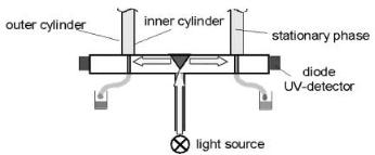
Fig. 4. Schematic drawing of the on-line UV detector in the P-CAC
umn while the column is rotated in a fast rotation mode (up to ten revolutions per minute). This guarantees a plane surface throughout the entire annulus.
3.4 UV-Detector
For monitoring the output of the annular column an online UV detector was developed [31] by Prior Separation Technology. In this case the P-CAC system is equipped with a separate measuring plate located directly under the slip-ring (see Fig. 4). The measuring plate contains 98 quartz capillaries, one for each of the outlets of the P-CAC and 8 reference channels. The online UV detection unit contains an external light source (UV lamp) and the light emitted (260 nm or 280 nm) by this light source is transferred through a quartz fiber to the center of the measuring plate. There the light beam is reflected on a conical mirror and is evenly distributed throughout the inner circumference of the measuring plate. The refracted light travels through the light path and hits the quartz capillary. Light is absorbed by the fluid stream in the capillary depending on the concentration of the molecules dissolved in the liquid stream according to the Lambert Beer Equation. The light portion being transmitted through one of the capillaries hits a diode creating a voltage signal. Corresponding to the 98 quartz capillaries there are 98 diodes wired in series and linked to a computer. On the computer a data-acquisition and monitoring software allows one to measure the absorbance and the elution position of the species which were separated in the annular column. The implementation of the on-line UV detector allows a continuous monitoring of all the products eluted from the P-CAC during the separation.
4
Mathematical Background – Theory
4.1
Analogy Between Fixed Bed and CAC
In fixed bed columns (batch columns), the fluid and solid phase concentrations are functions of both position and time. Considering a conventional, idealized,

Continuous Annular Chromatography |
243 |
stationary bed with void fraction e, a one-dimensional steady state, material balance for a solute with concentration C may be written as
e Dz |
∂2 C |
= e |
∂C |
+(1–e) |
∂q |
+u |
∂C |
, |
(1) |
2 |
∂t |
∂t |
∂ z |
||||||
|
∂ z |
|
|
|
|
|
where Dz is the axial dispersion coefficient, u is the superficial velocity, and C and q are the liquid and solid phase concentrations, respectively. Using a simple fluid film model to describe fluid-particle mass transfer, the following rate equation may be written to relate the fluid and solid phase concentrations [32]:
(1–e) |
∂q |
= k0a(C –C*) , |
(2) |
|
∂t |
||||
|
|
|
where ko a is an overall mass transfer coefficient and C* is the liquid phase concentration in equilibrium with the solid phase.
Continuity and rate equations can also be written in a cylindrical coordinate system for the two-dimensional annular chromatography.Assuming steady state and neglecting velocity and concentration variations in the radial direction, the above-mentioned equations may then be written as
|
∂2 C e Dq ∂2 C |
|
∂C |
|
∂q |
|
∂C |
|
||||||
e Dz |
|
+ |
|
|
|
= we |
|
+w(1–e) |
|
+u |
|
(3) |
||
∂z2 |
R20 |
∂q2 |
∂q |
∂q |
∂z |
|||||||||
and |
|
|
|
|
|
|
|
|||||||
w(1–e) |
|
∂q |
= k0 a (C –C*) , |
|
|
|
|
(4) |
||||||
|
|
|
|
|
|
|
||||||||
|
|
|
∂q |
|
|
|
|
|
|
|
||||
where Dz and Dq are the axial and the angular dispersion coefficients, Ro is the mean radius of the annular bed, w is the rate of rotation, and z and q are the axial and angular coordinates respectively. If angular dispersion is negligible, then the one-dimensional, unsteady-state, fixed bed equations (Eqs. 1 and 2) can be transformed into the corresponding steady-state, two-dimensional, continuous equations (Eqs. 3 and 4) with the change of variable:
q =wt´. |
(5) |
where w is the rotation rate, t´ is a transformed time, and q is the angle [33, 34]. Equations (3) and (4) then become
e Dz |
∂2 C |
= e |
∂C |
+(1–e) |
∂q |
+u |
∂C |
, |
∂z2 |
∂t¢? |
∂t¢? |
∂z |
and
∂q
(1–e) ∂t?¢ = k0 a(C –C*) .
(6)
(7)
These equations can be solved with the appropriate boundary conditions. For isocratic operation, for example, the boundary conditions may be written as

244 |
|
|
|
|
|
|
|
|
|
|
|
|
|
|
|
|
J. Wolfgang |
|
|
t¢ = 0, |
all z: |
q = c = 0 |
|
|
|
|
|||||||||
|
|
z = 0, 0 < |
|
|
|
C – |
e Dz |
|
f C |
= CF |
|||||||
|
|
t£≤tF¢F |
|
||||||||||||||
|
|
|
|
|
|
|
|||||||||||
|
|
|
|
|
|
|
|
|
|
|
u |
|
f z |
||||
|
|
|
|
|
|
|
|
|
|
|
|
||||||
|
|
|
t¢ > |
|
|
C – |
e Dz |
|
f C |
= 0 |
|||||||
|
|
|
tFF¢ |
|
|
||||||||||||
|
|
|
|
|
|||||||||||||
|
|
|
|
|
|
|
|
|
|
u |
f z |
||||||
|
|
|
|
|
|
f C |
|
||||||||||
|
|
z = Z, |
all t¢ |
= 0 |
|
|
|
|
|||||||||
|
|
|
|
|
|
|
|
|
|||||||||
|
|
|
|
|
|
f z |
|
|
|
|
|||||||
where C |
F |
is the feed concentration and t´ is the length of time corresponding to |
|||||||||||||||
|
|
|
|
|
|
|
|
|
|
|
|
|
|
|
|
F |
|
the feed arc
q =wt´ .
F F
Because of this analogy, the mathematical treatment of the steady-state performance of the CAC is no more complicated than the corresponding mathematical treatment of the analogous transient conventional chromatographic operation. Thus, solutions that are available to describe the latter can be used very simply to describe the former, making use of Eq. (5). This of course holds only if angular dispersion is negligible, which however is the case in most typical preparative or production-scale liquid chromatographic operations as shown by Howard and coworkers [10, 35].
4.2
Analytical Solution for the CAC Steady State Equation
An analytical solution of these mass-transfer equations for linear equilibrium was found by Thomas [36] for fixed bed operations. The Thomas solution can be further simplified if one assumes an infinitely small feed pulse (or feed arc in case of annular chromatography), and if the number of transfer units (n=k0 az/u) is greater then five. The resulting approximate expression (Sherwood et al. [37]) is
ˆ |
L F |
Ï |
|
(k0 a)2 |
|
¸0,25 |
Ï |
È |
k0a z |
|||||
C (z, t) = |
|
|
|
Ì |
|
|
|
˝ |
expÌ– Í |
|
– |
|||
2p |
0,5 |
3 |
ˆ |
3 |
|
|||||||||
|
|
|
Óu zt[(1–e)K] |
˛ |
Ó |
Î |
u |
|||||||
where |
|
q |
|
e z |
|
|
|
|
|
|
|
|||
ˆ |
= |
|
|
|
|
|
|
|
|
|||||
t |
|
|
– |
|
|
|
|
|
|
|
|
|
||
w |
|
u |
|
|
|
|
|
|
|
|||||
ˆ ˘2 k0at
˙
K(1–e) ˚
Ó Ì Ï
,
(8)
(9)
The amount of solute introduced per unit cross-sectional area of the sorbent bed, LF (Loading Factor), can be calculated from
|
C uQ |
|
360o |
|
|
LF = |
F F |
|
|
, |
(10) |
QT |
|
||||
|
|
w |
|
||
where QF is the feed flow rate and QT is the total flow rate.