

Physics of biomolecules and cells
.pdf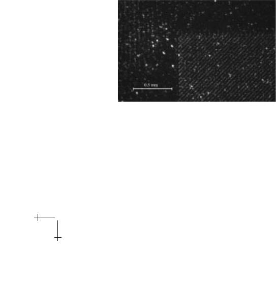
402 |
Physics of Bio-Molecules and Cells |
Once cells are labeled, the sample is fed into the main input channel at a high hydrodynamic pressure. The input channel is 40 µm wide and feeds into a central rectangular chamber. Bu er flows through multiple channels on both sides of the input at an even higher pressure. This confines the sample to a narrow stream as it flows through the chamber. The rationale behind this “N-port injector” has been discussed in earlier lectures, ad nauseaum no doubt.
The central chamber (5 mm × 18 mm) contains the magnetic structures and is where magnetic separation occurs. Wires of a ferromagnetic material are countersunk into the floor of the chamber at a 45o angle to the flow of cells. The wires are 10 µm wide and spaced 25 µm apart. The stripes were magnetized by placement in a 10 kG external magnetic field from an electromagnet. The high magnetic field gradient at the edge of each wire imposes a force on the superparamagnetic beads at an angle to the hydrodynamic force. The component of the magnetic force perpendicular to the flow causes the lateral deflection of all labeled cells. Cells are constrained to move along the magnetic wires by the large field gradients that exist at their edges. Figure [2] shows fluorescent images of magnetic beads.
Fig. 6. Magnetic wire array with paramagnetic beads bound to the edges of the strips where the magnetic field gradient is highest.
However, the undeflected cells must stay confined to a narrow stream across the length of the chamber in order for perpendicular deflections to be resolved. Channels are positioned at the sides and end of the chamber to capture cells as they exit. More than 350 channels, 24 µm wide, feed into nine outlets where cells are collected. All unlabeled cells will flow into the central outlet. In the outlets to the right, the fraction of labeled cells will be enriched. No cells should migrate to the left.

Lecture 4: Fractionating Cells |
403 |
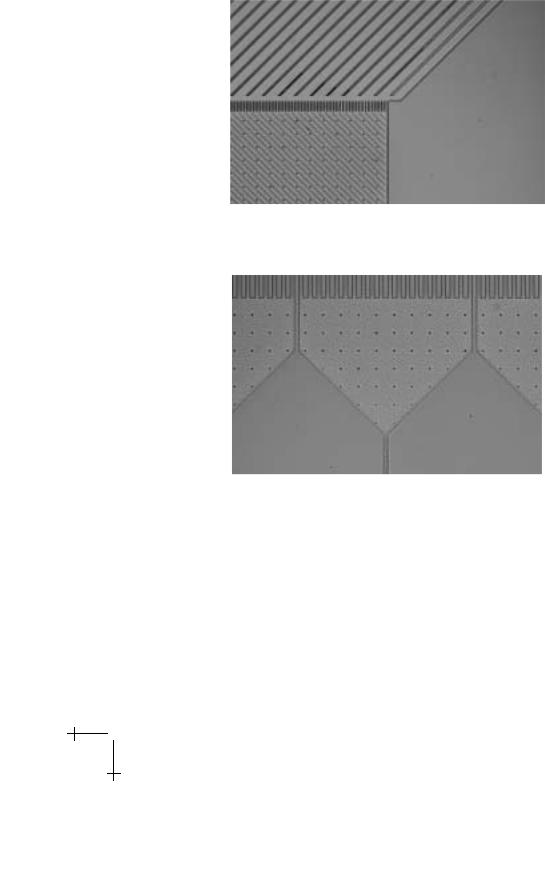
Fig. 7. Microscopic views of etched structures, before sputtering.
If cells can indeed be sorted by the high gradients in our device, rare cell types expressing known surface antigens can be isolated. Though its implications are the same as for FACS and MACS, our method comes with several unique advantages. First, it allows for the continuous input of cells. It therefore holds the promise of tolerating a large volume of cells with high e ciency. Second, its two-dimensional design allows simultaneous isolation of di erent cell types. By labeling di erent populations of cells with particles of di ering magnetic susceptibilities, one could expect di erent degrees of lateral separation. Third, its small size would make it a cheap and convenient mechanism for separating cells.
The central chamber (5 mm × 18 mm) contains the magnetic structures and is where magnetic separation occurs. Wires of a ferromagnetic material are countersunk into the floor of the chamber at a 45o angle to the flow of cells. The wires are 10 µm wide and spaced 25 µm apart. The high magnetic field gradient at the edge of each wire imposes a force on the superparamagnetic beads at an angle to the hydrodynamic force. The component of the magnetic force perpendicular to the flow causes the lateral deflection of all labeled cells. Cells are constrained to move along the magnetic wires by the large field gradients that exist at their edges. However, the undeflected cells must stay confined to a narrow stream across the length of the chamber in order for perpendicular deflections to be resolved.
Channels are positioned at the sides and end of the chamber to capture cells as they exit. More than 350 channels, 24 µm wide, feed into nine outlets where cells are collected. All unlabeled cells will flow into the central outlet. In the outlets to the right, the fraction of labeled cells will be enriched. No cells should migrate to the left. Figures 7–9 show images of various features of the fabricated wafer.
404 |
Physics of Bio-Molecules and Cells |
Fig. 8. Entrance to the central chamber. Magnetic wires are at a 45o angle to the input jet stream. Round dots are posts to prevent the coverslip from collapsing.
Fig. 9. Channels and outlets at the end of the central chamber.
Once a chip IS prepared with a coverslip, it is loaded onto a lucite chuck which mediated the flow of fluid (Fig. 10). The chuck was machined in the Princeton Physics Department machine shop. It is designed so that a high pressure could be applied to the fluid in all three inlets to drive it through the chip. Twelve tubes are drilled in the chuck so as to exactly line up with the holes in the chip. Fluid can enter the chip from the bottom, through the holes drilled at the inlets. It can then exit through one of the nine outlet holes in the chip, eventually filling up the tubes in the chuck that were exposed to atmospheric pressure. From there, the cells can be

Lecture 4: Fractionating Cells |
405 |
Fig. 10. Chuck assembly.
collected. The sealed chip is placed on top of the o-rings and held down by a rectangular steel frame. It is recommended that spring washers be used with the screws that hold down the frame so that the chip does not crack under stresses. However, controlling the flow through the input channels is not easy. Bubbles are a big obstacle to establishing hydrodynamic flow. Small bubbles that became trapped in the apparatus blocked o channels to flow. To work around this problem, the empty chuck was submerged in bu er before it was even assembled. The chip was then loaded onto the chuck, completely underwater. Additional problems came from loading the inlets with the syringe. The right angles in the input tubes turned out to be an awkward design for filling them. When bubbles are encountered, vacuum pumping of the chip under bu er can often liberate them. Otherwise, the chuck can be soaked overnight to let the bubbles gradually disappear.

406 |
Physics of Bio-Molecules and Cells |
7 A preliminary blood cell run
Since this is really a progress report on the development of a technology as we develop this idea it is unfortunate that we cannot present at this time pictures of cells labeled with magnetic beads separating in the device. However, we have been able to show at this point that whole blood samples can be run in the device and that ultra-narrow jets of cells can be run across the entire 2 cm length of the chip with precision, and that white blood cell adhesion to the device walls can be controlled.
White blood cell adhesion is a major problem because of the high concentration of proteins presented at the cell surface, particularly white blood cells. Our chip was fabricated out of silicon and has approximately a 0.2 micron thick silicon dioxide overcoat. However, silicon dioxide surfaces are highly charged and strongly bind cells to the surface. We have been exploring ways to avoid cell adhesion, and one of the most promising materials is the tri-block copolymer polyethylene oxide-polypropylene oxide-polyethylene oxide (PEO-PPO-PEO), also known as Pluronics under the manufacture of BASF. A good reference on the use of Pluronic surfactants to prevent the adhesion of cells to surfaces can be found in the papers of Karin Caldwell [27]. The great advantage of the Pluronic system is that the hydrophobic center bloc (PPO) can bind to hydrophobic surfaces of silicone elastomers (polydimethylsiloxane, PDMS) while the end group polyethylene oxide (also commonly known as polyethylene glycol, PEG) is a very unusual polymer that is neutral but very hydrophilic and strongly hydrogen bonding. If the PPO end groups and the center PPO group are chosen to be of the appropriate molecular weights, a very robust surface on a virgin PDMS surface can be created which does not bind proteins due to a combination of the shielding of the hydrophobic surface of PDMS by the Pluronics and an entropic repulsion of the surface PPO groups of the protein.
In our case, we used a 0.1% solution of Pluronic F108 from BASF (BASF Corporation, Mount Olive, NJ 07828) in a saline bu er to wet our magnetic array wafer that was sealed with a cover slip upon which a thin layer of PDMS had been spun and polymerized. Although PDMS is very hydrophobic and normally water will not penetrate a sealed PDMS structure, a saline bu er solution which contains 0.5% F108 will over a period of 24 hours penetrate and wet a sealed PDMS structure. This then provides a very interesting surface which is hydrophilic, uncharged and not “biofouling”.
Once the array was successfully wet and the surface passivated a 20 microliter sample of blood from a finger prick was put into Becton Dickinson Microtainer tube treated with lithium heparin to prevent clotting of the blood (Becton Dickinson, Franklin Lakes, NJ 07417-1885). The white blood cells in the blood sample were then stained with the vital

Lecture 4: Fractionating Cells |
407 |
Fig. 11. Brightfield image of blood at entrance to the array.
Fig. 12. Epifluorescence image of labeled white blood cells at entrance to the array.
nuclear stain Hoechst 33342 (Molecular Probes, Eugene, OR 97402-9165) by incubation at 37 ◦C for 30 min. The sample of stained blood was then loaded in the center chamber and positive air pressure of approximately 0.2 psi where applied to the center jet and the side fluid curtain flow.
Figure 11 shows in epi bright field illumination the blood sample at roughly ×40 magnification leading up to the injection jet. Figure 12 shows in epifluorescence the same blood sample only now the labeled white blood cells are visible. Figure 13 shows the stream of blood cells flowing from right to

408 |
Physics of Bio-Molecules and Cells |
Fig. 13. Brightfield image of blood cells flowing a) from injection port and b) in the center of the array about 1 cm in from the injection port.
left into the magnetic line array, illustrating how the hydrodynamics ensures a smooth non-expanding flow into a large open area, both at the entrance (a) and well within the array (b). No evidence of red blood cell adhesion to the device was seen. Figure 14 shows an image of two labeled white blood cells constrained within the red blood cell stream seen in Figure 13b, showing how the white cells move smoothly with the stream of red cells and show very little adhesion to the surface. Clearly, the next step now is to label these cells with paramagnetic antibody beads and deflect them from the main stream, but alas due to the deadline constraints of this paper that project remains to be done in the next several months.

Lecture 4: Fractionating Cells |
409 |
Fig. 14. Epifluorescence image of two white blood cells in (b) of Figure 13.
8 Conclusions
Progress has been made in constructing a magnetic cell separation device. However, its potential to fractionate cells remains unfulfilled. Several procedures still need to be optimized, and several experiments still need to be run. In this section, a few main areas are highlighted.
It is important to determine how to optimize the hydrodynamic forces in scale with the magnetic forces produced by the wires. Magnetic separation of beads must be demonstrated. If the hydrodynamic forces are so strong that they overshadow magnetic deflections, the pressure gradient must be diminished in a way that does not compromise the jet width. If instead the beads adhere to the wires, pressures may need to be increased. The electrostatic adhesion of beads to wires is a concern, in which case the SiO2 layer on top of the wires should be made thicker. At all points along the way, careful control experiments need to be conducted. Paramagnetic beads can be run alongside latex beads, preferably of two di erent colors.
Also, it will be important to have more confidence in handling cells. Labeling cells is crucial for achieving magnetic fractionation. Experimenting with di erent stains and di erent markers will likely determine a good test sample for the apparatus. Further, multiple markers and fluorescent stains will be necessary to conduct control experiments. Surface passivation measures must also be optimized in order to prevent the adhesion of cells to silicon structures.
