

Vankka J. - Digital Synthesizers and Transmitters for Software Radio (2000)(en)
.pdf90 Chapter 6
significant part of Ang may change the value of the bits of the least significant part with respect to their initial value in Ang. As a consequence, the parallel evaluation of the directions associated with the fine part can be performed only after rotations of the coarse one. The coarse rotator uses the whole rotation angle Ang and the initial vector coordinates I0 and Q0 to generate I , and Q at the end of the first iterations ( ≈ 1/3 N) [Wan97].
The rotation directions are generated sequentially, as in the conventional CORDIC algorithm. At the end of these iterations, the most significant part
of |
is zero. The fine rotator operates starting from I , and Q to generate |
|
I |
and Q at the end of the remaining N |
iterations. |
|
A method in [Ahm89] implements a coarse stage with CORDIC for the |
|
first rotations and a fine stage computing as a single rotation via two multiplications and without a trigonometric lookup table. A coarse stage is implemented with CORDIC rotator and the fine stage by a lookup table and multipliers in [Cur01]. Applying the Taylor series expansions to the trigonometric functions in (6.1), and taking only the first terms, (6.1) becomes
IN |
In |
+ Qn |
AngL |
|
|
|
(6.26) |
QN |
Qn In AngL |
||
Therefore, no look-up tables for sine and cosine terms are needed to complete the fine rotation according to (6.26) [Ahm89].
6.4.2 Partitioned-Hybrid CORDIC Algorithm
To increase the performance, the computation of the coarse rotation must be completely separated from the least significant one while preserving full accuracy. To achieve this goal, the Ang is partitioned in two parts: the n most significant bits (AngH) and the remaining N n bits (AngL). The rotation Ang is partitioned in two rotations; AngH is the most relevant, while AngL adjusts the position of the rotated vector to achieve the final expected (or
Ang |
|
|
|
|
|
|
|
|
|
|
|
|
|
|
|
AngH |
|
AngL |
|
|
|||
|
|
|
|
|
|
|
|
I0 |
|
|
|
In |
|
IN |
|
|
|
COARSE |
|
|
FINE |
|
|
|
|
ROTATOR |
|
|
ROTATOR |
|
|
Q0 |
|
|
|
Qn |
|
QN |
|
|
|
|
|
|
|
|
|
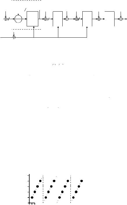
Figure 6-3. The architecture for Partitioned-Hybrid CORDIC algorithms.

CORDIC Algorithm |
91 |
nearby) position. AngL always has zeros in the n most significant bits. The angle AngH is completely independent from AngL only if it does not change the N n least significant bits of the residue rotation angle with respect to AngL. To achieve this goal, the exact rotation AngH must be performed separately from AngL. To avoid a possible increase in the number of the rotation iterations and to speed up the whole algorithm, the traditional CORDIC algorithm is modified by assuming that the whole rotation AngH is performed in only one iteration [Wan97]. This is not an actual limit since, when n is not too large, the iteration can be realized by using a ROM-based architecture.
The architectural approach to the case of the Partitioned-Hybrid CORDIC algorithm is given in Figure 6-3. The coarse rotator operates a rotation of AngH on I0 and Q0 and generates In and Qn . The fine rotator receives these intermediate rotated coordinates and applies the rotation AngL to generate the final IN and QN. The coarse rotator could be implemented by the look-up table, where the AngH is used as an address. This solution is feasible in terms of circuit complexity only for relatively small values of n, as occurs in several applications [Mad99], [Jan02]. A coarse stage is implemented with lookup tables and multipliers in [Ahm89], [Tor03] or by a lookup table [Jan02]. The fine rotator could be implemented as a single rotation using approximation (6.26) in [Ahm89], [Tor03] or by CORDIC iterations using [Ahm89], [Mad99], [Jan02]. The rotation directions for the CORDIC iterations are obtained from (6.25), which reduces the latency time.
The coarse rotation stage performs the rotation with the AngH using a complex multiplier in [Son03], [Tor03]. The sin(AngH) and cos(AngH) required for this rotation are stored in a small lookup table. To reduce the hardware cost of the complex multiplication, sin(AngH) and cos(AngH) are quantized on a small number of bits in [Son03]. Naturally, this brute quantization introduces a significant angle rotation error. To avoid this situation, the angle rotation error of the coarse rotation stage is stored in a lookup table and taken into consideration by the fine rotation block [Son03]. The fine rotation is also performed using a complex multiplier, but the sin(AngL) and cos(AngL) are computed using Taylor series expansion (6.26) [Tor03] or linear interpolation [Son03]. Even if these algorithms require two complex multipliers, the total area is smaller than the one of a classic mixer due to the fact that the wordlength of the multipliers is small [Tor03]. However, in order to reach high operation speed, both designs have to rely on heavy pipelining. For instance, the design in [Tor03] has 13 pipeline stages for a 300 MHz clock, whereas the design in [Son03] requires 17 pipeline stages for a 330 MHz clock. Therefore, these architectures have the same drawback as the CORDIC algorithm, i.e., high tuning latency.
92 |
Chapter 6 |
REFERENCES
[Ahm82] H. M. Ahmed, "Signal Processing Algorithms and Architectures," Ph. D. dissertation, Department of Electrical Engineering, Stanford University, CA. Jun. 1982.
[Ahm89] H. M. Ahmed, "Efficient Elementary Function Generation with Multipliers," in Proc. 9th Symposium on Computer Arithmetic, Santa Monica, CA, USA, Sept. 1989, pp. 52-59.
[Ahn98] Y. Ahn, and S. Nahm, "VLSI Design of a CORDIC-based Derotator," in Proc. ISCAS’98, Vol. 2, June 1998, pp. 449-452.
[Bu88] J. Bu, E. F. Deprettere, and F. du Lange, "On the Optimization of Pipelined Silicon CORDIC Algorithm," in Proc. European Signal Processing Conference (EUSIPCO), Sep. 1988, pp. 1,227-1,230.
[Cav88a] J. R. Cavallaro, and F. T. Luk, "Floating Point CORDIC for Matrix Computations," in Proc. IEEE International Conference on Computer Design, Oct. 1988, pp. 40-42.
[Cav88b] J. R. Cavallaro, and F. T. Luk, "CORDIC Arithmetic for a SVD processor," Journal of Parallel and Distributed Computing, Vol. 5, pp. 271290, June 1988.
[Coc92] D. Cochran, "Algorithms and Accuracy in the HP-35," Hewlett Packard Journal, pp. 10-11, Jun. 1992.
[Cur01] F. Curticãpean, and J. Niittylahti, "An Improved Digital Quadrature Frequency Down-Converter Architecture," Asilomar Conf. on Signals, Syst. and Comput., Nov. 2001, pp. II-1318-1321.
[Dac98] M. Dachroth, B. Hoppe, H. Meuth, and U. W. Steiger, "High-Speed Architecture and Hardware Implementation of a 16-bit 100 MHz Numerically Controlled Oscillator," in Proc. ESSCIRC’98, Sept. 1998, pp. 456-459. [Daw96] H. Dawid, and H. Meyr, "The Differential CORDIC Algorithm: Constant Scale Factor Redundant Implementation without Correcting Iterations," IEEE Trans. on Computers, Vol. 45, No. 3, pp. 307-318, Mar. 1996.
[Dup93] J. Duprat, and J. M. Muller, "The CORDIC Algorithm: New Results for Fast VLSI Implementation," IEEE Trans. on Computers, Vol. 42, No. 2, pp. 168-178, Feb. 1993.
[Dur87] R. A. Duryea, and C. Pottle, "Finite Precision Arithmetic Units in Jacobi SVD Architectures," School of Electrical Engineering, Cornell University, Ithacaa, NY, Technical Report EE-CEG-87-11, Mar. 1987.
[Erc88] M. D. Ercegovac, and T. Lang, "Implementation of Fast Angle Calculation and Rotation Using On-Line CORDIC," in Proc. IEEE International Symposium on Circuits and Systems (ISCAS), June 1988, pp. 2,703-2,706.
[Erc90] M. D. Ercegovac, and T. Lang, "Redundant and On-Line CORDIC Application to Matrix Triangularization and SVD," IEEE Trans. on Computers, Vol. 38, No. 6, pp. 725-740, June 1990.
CORDIC Algorithm |
93 |
[Fre95] S. Freeman, and M. O’Donnell, "A Complex Arithmetic Digital Signal Processor Using Cordic Rotators," in Proc. ICASSP-95, Vol. 5, pp.
3191-3194, May 1995.
[Hav80] G. L. Haviland, and A. A. Tuszynski, "A CORDIC Arithmetic Processor Chip," IEEE Trans. on Computers, Vol. 29, No. 2, pp. 68-79, Feb.
1980.
[Hsi95] S. F. Hsiao, and J. M. Delosme, "Householder CORDIC Algorithms," IEEE Trans. Comput., Vol. 44, No. 8, pp. 990-1001, Aug. 1995. [Hu92a] Y. H. Hu, "The Quantization Effects of the CORDIC Algorithm," IEEE Trans. Signal Processing, Vol. 40, No. 4, pp. 834-844, April 1992. [Hu92b] H. Y. Hu, "CORDIC-Based VLSI Architectures for Digital Signal Processing," IEEE Signal Processing Magazine, pp. 16-35, July 1992. [Hwa03] D. D. Hwang, D. Fu, and A. N. Willson, Jr, "A 400-MHz Processor for the Conversion of Rectangular to Polar Coordinates in 0.25- m CMOS," IEEE J. Solid-State Circuits, Vol. 38, , No. 10, pp. 1771-1775, Oct. 2003. [Jan02] I. Janiszewski, B. Hoppe, and H. Meuth, "Numerically Controlled Oscillators with Hybrid Function Generators," IEEE Transactions on Ultrasonics, Ferroelectrics and Frequency Control, Vol. 49, pp. 995-1004, July
2002.
[Kot93] K. Kota, and J. R. Cavallaro, "Numerical Accuracy and Hardware Tradeoffs for CORDIC Arithmetic for Special-Purpose Processors," IEEE Trans. Comput., Vol. 42, No. 7, pp. 769-779, July 1993.
[Kun90] H. Kunemund, S. Soldner, S. Wohlleben, and T. Noll, "CORDIC Processor with Carry Save Architecture," in Proc. ESSCIRC’90, Sep. 1990, pp.193-196.
[Lan88]A. A. de Lange, A. J. van der Hoeven, E. F. Deprettere, and J. Bu, "An Optimal Floating-Point Pipeline CMOS CORDIC Processor," in Proc. IEEE International Symposium on Circuits and Systems (ISCAS), June 1988, pp. 2,043-2,047.
[Lee89] J. Lee, and T. Lang, "On-Line CORDIC for Generalized Singular Value Decomposition," SPIE High Speed Computing II Vol 1058, pp.235247, 1989.
[Lee92] J. Lee, and T. Lang, "Constant-Factor Redundant CORDIC for Angle Calculation and Rotation," IEEE Trans. Comput., Vol. 41, No. 8, pp. 1016-1025, Aug. 1992.
[Lin90] H. X. Lin, and H. J. Sips, "On-Line CORDIC Algorithms," IEEE Trans. on Computers, Vol. 38, No. 8, pp. 1,038-1,052, Aug. 1990.
[Mad99] A. Madisetti, A. Kwentus, and A. N. Wilson, Jr., "A 100-MHz, 16- b, Direct Digital Frequency Synthesizer with a 100-dBc Spurious-Free Dynamic Range," IEEE J. of Solid State Circuits, Vol. 34, No. 8, pp. 1034-
1044, Jan. 1999.

94 |
Chapter 6 |
[Nol90] T. Noll, "Carry-Save Arithmetic for High-Speed Digital Signal Processing," in Proc. IEEE International Symposium on Circuits and Systems (ISCAS), Vol. 2, May 1990, pp. 982-986.
[Nol91] T. Noll, "Carry-Save Architectures for High-Speed Digital Signal Processing," Journal of VLSI Signal Processing, Vol. 3, pp. 121-140, June 1991.
[Not88] S. Note, J. van Meerbergen, Catthoor, and H. de Man, "Automated Synthesis of a High Speed CORDIC Algorithm with the Cathedral-III Compilation System," in Proc. IEEE International Symposium on Circuits and Systems (ISCAS), June 1988, pp. 581-584.
[Par93] B. Parhami, "On the Implementation of Arithmetic Support Functions for Generalized Signed-Digit Number Systems," IEEE Trans. on Computers, Vol. 42, No. 3, pp. 379-384, Mar. 1993.
[Phi95] L. Philips, I. Bolsens, and H. D. Man, "A Programmable CDMA IF Transceiver ASIC for Wireless Communications," in Proc. IEEE Custom Integrated Circuits Conf., 1995, pp. 307-310.
[Sar98] R. Sarmiento, and et al., A CORDIC Processor for FFT Computation and Its Implementation Using Gallium Arsenide Technology, IEEE
Trans. on VLSI Systems, Vol. 6, No. 1, pp. 18-30, Mar. 1998.
[Sch86] G. Schmidt, D. Timmermann, J. F. Bohme, and H. Hahn, "Parameter Optimization of the CORDIC Algorithm and Implementation in a CMOS Chip," in Proc. European Signal Processing Conference (EUSIPCO), Sep. 1986, pp. 1,291-1,222.
[Son03] Y. Song and B. Kim, "A 330-MHz 15-b Quadrature Digital Synthesizer/Mixer in 0.25 m CMOS," in Proc. 29th European Solid-State Circuits Conference, Estoril, Portugal, Sept. 2003, pp. 513-516.
[Tak87] N. Takagi, T. Asada, and S. A. Yajima, "Hardware Algorithm for Computing Sine and Cosine using Redundant Binary Representation," Systems and Computers in Japan, Vol. 18, No. 9, pp. 1-9, 1987.
[Tak91] N. Takagi, T. Asada, and S. A. Yajima, "Redundant CORDIC Methods with a Constant Scale Factor for a Sine and Cosine Computation," IEEE Trans. on Computers, Vol. 40, No. 9, pp. 989-995, Sep. 1991.
[Tim89] D. Timmermann, H. Hahn, and B. Hosticka, "Modified CORDIC Algorithm with Reduced Iterations," Electronics Letters, Vol. 25, No. 15, pp. 950-951, July 1989.
[Tim91] D. Timmermann, H. Hahn, B. J. Hostica, and B. Rix, "A New Addi-
tion Scheme and Fast Scaling Factor Compensation Methods for CORDIC Algorithms," INTEGRATION, the VLSI Journal, Vol. 11, pp. 85-100, 1991. [Tor03] A. Torosyan, D. Fu, and A. N. Willson, Jr., "A 300-MHz Quadrature Direct Digital Synthesizer/Mixer in 0.25 m CMOS," IEEE J. of Solid State Circuits, Vol. 38, No. 6, pp. 875-887, June 2003.
[Vol59] J. E. Volder, "The CORDIC Trigonometric Computing Technique," IRE Trans. on Electron. Comput., Vol. C-8, pp. 330–334, Sept. 1959.
CORDIC Algorithm |
95 |
[Wal71] J. S. Walther, "A Unified Algorithm for Elementary Functions," in Proc. Spring Joint Computer Conference, May 1971, pp. 379-385.
[Wan97] S. Wang, V. Piuri, and E. E. Swartzlander, "Hybrid CORDIC Algorithms," IEEE Trans. on Computers, Vol. 46, No. 11, pp. 1202-1207, Nov. 1997.
[Yos89]H. Yoshimura, T. Nakanishi, and H. Yamauchi, "A 50 MHz CMOS Geometrical Mapping Processor," IEEE Trans. on Circuits and Systems, Vol. 36, No. 10, pp. 1,360-1,363, 1989.

Chapter 7
7. SOURCES OF NOISE AND SPURS IN DDS
The model of the noise and spurs in the DDS has six sources. These sources are depicted symbolically in Figure 7-1. The sources are: the truncation of the phase accumulator bits addressing the sine LUT (eP), a distortion from
compressing the sine LUT (eCOM), the finite precision of the sine samples stored in the LUT (eA), the digital-to-analog conversion (eDA) (see Chapter 10), a post-filter (eF), the phase noise of the clock (nclk), and the frequency error ( f). The frequency error ( f) causes a frequency offset (4.2), but not noise and spurs.
7.1 Phase Truncation Related Spurious Effects
In the ideal case, with no phase and amplitude truncation, the output sample sequence of the DDS is given by
s(n) sin(2π |
∆P |
n). |
(7.1) |
|
|||
|
2 j |
|
|
Since the amount of memory required to encode the entire width of the phase accumulator would usually be prohibitive, only k of the most significant bits of the accumulator output are generally used to calculate the sine-wave samples. If the phase accumulator value is truncated to k bits prior to performing the look-up operation, the output sequence must be modified as
s(n) sin(2π |
|
ª ∆P |
n |
º |
|
), |
(7.2) |
||
|
|
2k |
|
¬2 j k |
¼ |
|
|
|
|
|
|
|
|||||||
where [] denotes truncation to integer values. This may be rewritten as |
|
||||||||
s(n) sin( |
2π |
(∆Pn |
eP (n))), |
(7.3) |
|||||
|
|||||||||
|
2 j |
|
|
|
|
|
|||
98 |
|
|
|
|
|
|
|
|
|
|
|
|
Chapter 7 |
|
|
|
|
|
|
|
|
|
|
|
|
|
|
|
|
PHASE ACCUMULATOR |
|
|
|
|
|
|
|||||
|
∆f |
j |
|
|
|
|
|
e P |
|
e COM e A |
|
e DA |
e F |
|
|
|
|
|
|
|
PHASE |
D/A- |
|||||
|
j |
|
|
PHASE |
|
|
|
|
|
||||
P |
|
|
|
k |
TO AMP- |
m |
|
FILTER |
|||||
|
|
|
CON- |
|
|||||||||
|
|
REGIS- |
|
||||||||||
|
|
|
|
|
LITUDE |
|
|
||||||
|
|
|
|
|
|
|
VER- |
|
|
||||
|
|
|
|
TER |
|
|
|
|
|
||||
|
|
|
|
|
|
|
|
CONVER- |
|
|
fout |
||
|
|
|
|
|
|
PHASE |
AMPLITUDE TER |
|
|||||
|
|
|
|
|
|
|
|||||||
|
|
|
|
|
|
|
|
|
TER |
|
|
|
|
|
|
|
|
|
|
|
|
|
|
|
|
|
|
nclk
Figure 7-1. Block diagram of the sources of noise and spurs.
where eP(n) is the error associated with the phase truncation. The phase error sample sequence is also restricted in magnitude as
|
|
P |
( |
|
) |
2 j k |
(7.4) |
|
|
|
and is also periodic with some period. The phase truncation occurs only when GCD (∆P, 2j) is smaller than 2j k. If GCD (∆P, 2j) is equal or greater than 2j k, then the phase increment bits are zeros below 2j k and no phase error occurs.
This sawtooth waveform (see Figure 7-2) is identical to the waveform that would be generated by a phase accumulator of word length (j-k) with an input phase increment word of
( |
|
∆P) mod 2 j k |
(7.5) |
A complete derivation of the phase accumulator truncation effects on the output spectrum is given in [Meh83], [Nic87], [Jen88b], [Kro00], [Tor01]. References [Meh83] and [Nic87] describe very similar approaches and base their analyses on the phase-error sequence due to phase truncation and, using properties of this error sequence along with the assistance of small-angle approximations, derive a rather complex procedure for the characterization of phase-truncation spurs. Kroupa [Kro00] used an approach similar to that of [Meh83] and [Nic87] and presented an algorithm for the estimation of phase-truncation spurs with the introduction of more approximations. Jenq [Jen88b] used a more elegant approach, one for analyzing a class of non-
eP(n)
2j-k


 n
n
Figure 7-2. Phase accumulator error sequence.

Sources of Noise and Spurs in DDS |
99 |
uniformly sampled signals, to model the phase error due to phase truncation without approximations. References [Jen88b] and [Tor01] describe similar approaches. The difference between them is that, in reference [Jen88b], the results are given in Fourier spectrum, while in [Tor01], the result are given in discrete Fourier transform, which comprise just the samples of the Fourier transform.
The process of phase truncation occurs in a periodic pattern due to the periodic characteristics of the DDS. Jenq obtains the equivalence of the phase truncation with a non-uniform sampling process [Jen88b]. The phase increment (∆P) is a number with an integer part W and a fractional part L/M i.e.
∆P |
W L / M |
(7.6) |
where L and M have no common factor. The integer part of the address increment register should be set to W, and its fractional part to L/M. Only the integer part of the phase accumulator is supplied to the addressing circuit of the sine LUT; data points sent to the D/A converter are offset from the intended uniform sampling instances, except for those where the fractional part of the phase accumulator is zero. Since the ratio of M to L is prime, M is the smallest integer to make M∆ P = M (W + L/M) an integer. Therefore, the output data sequence is obtained by sampling the sine wave stored in the sine LUT non-uniformly, but having an overall period MTs, where M is
M |
2 j k |
|
|
(7.7) |
|
|
||
|
GCD(∆P 2 j k ) |
|
and where GCD (∆P, 2j k) denotes the greatest common divisor of ∆P and 2j k. The number of spurs due to the phase truncation is [Nic87]
|
2 j− k |
|
|
Y |
|
1 M 1 |
(7.8) |
|
|||
|
GCD(∆P 2 j− k ) |
|
|
It has been shown in [Jen88a] that if one samples a sinusoidal e non-uniformly with sampling advancement offsets (i.e. sampling earlier than it should be) {tm Ts m = 0, 1, 2, … M-1}, then the digital spectrum of the sampled waveform is given by
|
|
G(ω ) |
1 |
¦ A(r) 2 π δ [ω |
|
|
ω |
|
|
|
|
|
|
|
|
|
|
|
π |
|
|
|
|
|
|
] |
(7.9) |
||||
T |
|
|
|
|
|
|
|
|
|
|
|
|
|
|
|
|
|
|
|
|
|||||||||||
|
|
|
s r − |
|
|
|
|
|
|
|
|
|
|
|
|
|
|
|
|
|
|
|
|
|
|
|
|
|
|
|
|
where the coefficient A(r) is given by |
|
|
|
|
|
|
|
|
|
|
|
|
|
|
|
|
|
|
|
|
|
|
|
||||||||
|
|
|
|
M 1 |
ª 1 |
|
|
|
|
|
º |
|
|
|
|
|
|
|
|
|
|
|
|
|
|
|
|
|
|
||
|
|
A(r) |
¦ |
e j2 tm |
fout / fs |
|
e j r m (2 |
/ M ) |
(7.10) |
||||||||||||||||||||||
|
|
|
|
|
|
|
|
|
|
||||||||||||||||||||||
|
¬M |
|
|
|
|
|
|
|
|||||||||||||||||||||||
|
|
|
|
m 0 |
|
|
|
|
|
|
¼ |
|
|
|
|
|
|
|
|
|
|
|
|
|
|
|
|
|
|
||
|
|
|
|
|
|
|
|
|
|
|
|
|
|
|
|
|
|
|
|
|
|
|
|
|
|
|
|||||
and f |
|
= 1/Ts and fout = |
out/2 |
|
|
|
|
|
|
|
|
|
|
|
|
|
|
|
|
|
|
|
|
|
|
|
|
|
|
|
|
|
|
|
|
|
|
|
|
|
|
|
|
|
|
|
|
|
|
|
|
|
|
|
|
|
|
|
|
||||

100 |
Chapter 7 |
To utilize (7.9) and (7.10) for this situation, let ∆ be the time duration corresponding to
|
|
(W + L / M ) ∆ |
|
Ts |
(7.11) |
||||||||||||||||||
and let [x]frac be the fractional part of x, then we then have |
|
||||||||||||||||||||||
t |
|
/ f |
|
|
|
|
|
t |
|
|
|
T |
|
|
|
|
|||||||
|
m[ |
|
|
s |
|
m |
|
s |
]frac ∆ |
(7.12) |
|||||||||||||
|
|
|
|
|
|
|
|
|
|
|
|
|
|
|
|
||||||||
|
|
[ |
|
|
|
|
|
|
|
|
|
|
]frac ∆ |
|
|||||||||
|
|
|
|
|
|
|
|
|
|
|
|
|
1 |
|
|
||||||||
|
|
|
|
|
|
|
|
|
|
|
|
|
|
|
|||||||||
fout |
|
|
|
|
(W + L / M ) ( |
), |
(7.13) |
||||||||||||||||
|
|
|
|
|
|||||||||||||||||||
|
|
|
|
|
|
|
|
|
|
|
|
|
|
|
|
|
|
|
|
|
NTs |
|
|
where N is 2k (k is the number of bits used to calculate the sine-wave samples).
Hence
2π tm fout / fs 2π [ |
|
|
|
|
|
|
|
]frac / N |
|
|
|
|
|
|
|||
|
|
|
|
|
|
|||
2π mL M , |
(7.14) |
|||||||
|
|
|
|
|||||
M N |
|
|
|
|
||||
where ¢mL²M stands for mL modulo M. Substituting (7.14) into (7.10), we then have
|
|
A(r |
L, M N) |
M 1 |
ª 1 |
e |
j2 m L |
M /(M N ) º |
j r m2 / M |
|
(7.15) |
||
|
|
¦ |
|
|
|
e |
|
|
|||||
|
|
|
|
|
m 0 |
¬M |
|
|
¼ |
|
|
|
|
It is noted from (7.15) that the finite sequence [A( |
L M N), |
= 0, 1,…, M - |
|||||||||||
1] |
is the |
discrete |
Fourier |
transform (DFT) |
of |
the sequence |
[(1/M) |
||||||
j |
tm fout |
fs |
= 0, |
1,…, M - 1]; therefore, by Parseval’s theorem, the sum |
|||||||||
|
|
|
|||||||||||
of the squares of A( |
L M N) « for |
= 0, 1,…, M – 1 is equal to M times |
|||||||||||
the sum of the squares of |
(1/M) |
j |
tm fout fs |
which is unity, i.e. |
|
||||||||
|
|
|
|
|
M 1 |
|
|
|
|
|
|
|
|
|
|
|
|
|
¦ A(r |
L M N) 2 |
1 |
|
|
|
(7.16) |
||
|
|
|
|
|
r 0 |
|
|
|
|
|
|
|
|
This result is used to calculate the S/N, which is defined as the ratio of the power of the desirable harmonic component to the sum of the powers of the spurious harmonic components, i.e.
ª |
A(0 L M N) 2 |
º |
||||
S / N 10 log10 |
A(0 L M N) 2 |
(7.17) |
||||
|
|
¬1 |
¼ |
|
|
|
|
|
|||||
|
|
|||||
where A(0, L M N) 2 can be readily obtained from (7.15)