

01_elektor_electronics_UK_january_2006
.pdfFREE VB COURSE
JANUARY 2006
£3.80
www.elektor-electronics.co.uk
™xHRKCQIy451128zv!:,
Yes, that's right, down town, down under in Sydney Australia. We are a bunch of electronics enthusiasts who sell a great range of goodies through our FREE 400 page catalogue. Don't be frightened! You can purchase on the Net from us 24/7/365 through our secure encrypted system. Post and packing charges are modest and you can have any of 8000+ unique products delivered to your door within 7 - 10 days of your order. Some specific products are shown below.
KC5414Lead-Acid Battery Zapper Kit
KC-5414 £11.75 + post & packing This kit uses high-energy pulses to
reverse the damaging effects of plate sulphation
and extends the life in wet-cell batteries. Supplied with case, leads, and
all electronic components.
"Clock Watcher’s"
LED Clock Kits
KC-5416(blue) £55.25 + post & packing  KC-5404(red) £41.75 + post & packing
 These clocks are hypnotic!
  They consist of an AVR driven clock circuit, that
also produces a dazzling display with the 60 LEDs around the
perimeter. It looks amazing, but can't be properly explained here. We have filmed it in action so you can see for yourself on our website www.jaycarelectonics.co.uk! Kit supplied with double sided silkscreened plated through hole PCB and all board components as well as the special clock housing! Available in Red (KC-5404) and Blue (KC-5416).
Choke A
GT-3095 £8.50 packing
Relieve stress with violence! This chicken dances around and squawks.
Funny for about one second! Grab
him by the throat and he screams
gags. Funny forever! (not recommended
children) •Approx 300mm tall.
•Requires 4 x AA batteries (not incl.)
We Stock...
Electronic Components,
Sub-Assemblies & Electronic Kits
Power Products
& Accessories
Audio & Visual Equipment
& Accessories
Computer & Telecoms
Accessories
Burglar Alarms &
Surveillance Equipment
Lighting Products
& Accessories
Gadgets & Unique Gifts
Theremin Synthesiser Kit
KC-5295 £14.75 + post & packing
The Theremin is a weird musical instrument that was invented early last century but is still used today. The Beach Boys' classic hit "Good Vibrations" featured a Theremin. By moving you hand between the antenna and the metal plate, you can
create strange sound effects. Kit includes a machined, silk screened, and pre drilled case, board, all electronic components,
and clear English instructions.
9VDC wall adaptor required (Maplin #GS74R £9.99).
Universal High Energy Ignition
KC-5419 £27.75 + post & packing |
|
|
|
Now with PIC. |
New |
& |
|
A high energy 0.9ms spark |
|
||
Improved |
|||
burns fuel faster and more |
|||
|
|
||
efficiently to give you more power! This versatile kit can be connected to conventional points, twin points or reluctor ignition systems. Includes PCB, case and all
electronic components.
High Performance Electronic Projects for Cars
BS-5080 £7.00 + post & packing
Australia's leading electronics magazine Silicon Chip, has developed a range of projects for performance cars. There are 16 projects in total, ranging from devices for remapping fuel curves, to nitrous controllers. The book includes all instructions, components lists, colour pictures, and circuit layouts. There are also chapters on engine management, advanced systems and DIY modifications. Over 150 pages! All the projects are available in kit form.
Smart Fuel Mixture Display |
High Performance Timer |
KC-5374 £8.95 + post & packing
This new ‘smart’ version has a few additional touches such as, auto dimming for night driving, emergency lean-out alarm, and better circuit protection. Another great feature, is the ‘dancing’ display which operates when the ECU is operating in closed loop. Kit supplied with PCB and all electronic components.
•Car must be fitted with air flow and EGO sensors (standard on all EFI systems) for full functionality.
KC-5379 £12.95 + post & packing
This sophisticated timer can be adapted for two modes of operation. The first is ‘one shot’ operation, which can be used to keep electric windows active, or a thermo fan running for a period after ignition is switched off etc. The second is a ‘pulse’ type operation, which can be used to squirt water spray for 1 second every 9 seconds. The time is adjustable via easy to use (and accurate) digital switches. Kit supplied with PCB, and all electronic
components.
Recommended box UB3 £1.40 each
400+ page Catalogue
Post and Packing Charges:
Order Value |
Cost |
£20 - £49.99 |
£5 |
£50 - £99.99 |
£10 |
£100 - £199.99 |
£20 |
£200 - £499.99 |
£30 |
£500+ |
£40 |
Max weight 12lb (5kg) - heavier parcels POA. Minimum order £20.
Log on to www.jaycarelectronics.co.uk/elektor
for your FREE catalogue!
0800 032 7241
(Monday - Friday 09.00 to 17.30 GMT + 10 hours only). For those who want to write:
100 Silverwater Rd Silverwater NSW 2128
Sydney AUSTRALIA


Miscellaneous matters
News from www.elektor-electronics.co.uk
Unfortunately, on 18 and 19 November last, our webserver was overloaded to the extent of being inaccessible for about 20 hours. We apologise to our customers who were unable to use the website at that time. With the publication of this January 2006 issue we should have an additional webserver up and running to handle the increasing amount of traffic our website is generating, mainly due to overseas customers downloading entire issues. Below is a Top-10 list for your amusement!
Jan Buiting, Editor
Top-10, Paid Downloads (magazine articles)
1Design Your Own IC, Part 2
2OBD-2 Analyser
3PPP HiFi Valve Power Amplifier
4Delphi for Electronic Engineers (1)
5ClariTy 2x300W Class-T Amplifier (1)
6High-End-Preamp, Part 1
7Build Your Own DRM Receiver
8Delphi for Electronic Engineers (2)
9GPS Receiver on USB
10Delphi for Electronic Engineers (3)
Publisher’s Announcement
Effectively from 1 November 2005 we have a new, central, address for editorial, subscriptions and sales:
Elektor Electronics (Publishing)
Regus Brentford
1000 Great West Road
Brentford TW8 9HH
United Kingdom
Tel. (+44) (0)208 2614509
Fax (+44) (0)208 2614447
All company email addresses remain unchanged; please see our website at www.elektor-electronics.co.uk.
We also take this opportunity to inform you of our new bank account:
Elektor Electronics (Publishing) / Segment bv
ABN-AMRO Bank, London Account no.: 40209520
IBAN: GB35 ABNA 4050 3040 2095 20 BIC: ABNAGB2L
We thank all customers and subscribers for using the new address and bankers’ data.
Paul Snakkers, Publisher.
elektor
lectronics
leading the way
28SMD Reflow Soldering Oven
It’s usually possible to solder ‘ordinary’ SMD components using a lowpower soldering iron and small-gauge solder. However, it’s a completely different story when you have to solder a component in a BGA, CSP or similar package. Such components can actually only be soldered using a reflow soldering oven. Here we describe how a normal, inexpensive oven can be transformed into a reflow oven.
22 The Battle against Electronic Waste
The EU has taken two significant steps in the fight against toxic electronic waste. In this article we look at what ‘RoHS’ and ‘WEEE’ mean for equipment manufacturers, distributors and users.
CONTENTS
Free Visual Basic for Electronics booklet with this issue
(secured to magazine outside covers)
Now is the time to step into action if you are after that one elusive part for your project or repair job. Concentrate on What and Where, surf, dig, unearth, bargain and rummage around. The Old Curiosity Shop may be closer to you than you think.
16 Part Mining
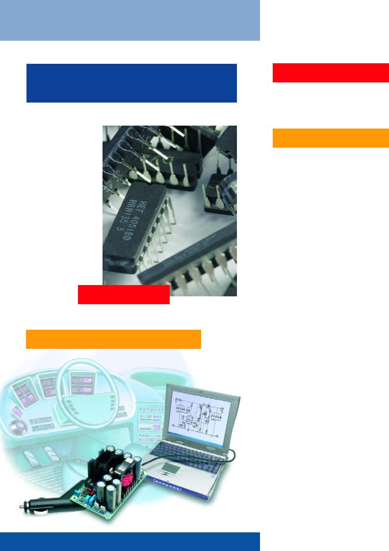
42 95-watt Laptop PSU Adaptor
Laptop or notebook computer users will invariably need to plug into a mains outlet from time to time to
top up the batteries. The car cigarette lighter socket in the car is also an electrical outlet but it can only supply 12 V. That’s no problem for the Laptop PSU Adaptor described here; it can deliver ample voltage and current for today’s portable computers from a car battery.
Volume 32 January 2006 no. 350
know-how
16 Part Mining
22The Battle against Electronic Waste
hands-on
28 SMD Reflow Soldering Oven
36 The R8C Family
42 95-watt Laptop PSU Adaptor
50 Shutter Time Meter
56Automatic
Attic Window Controller
62 |
A ‘Retro’ Mobile Phone |
66 |
Timer Switch |
|
for Washing Machine |
72 |
Design Tips |
|
Four Steps to LEDs on the Mains |
|
Christmas Tree Lighting with LEDs |
|
Poor Man’s CRT Demagnetizer |
|
|
technology |
54 |
E-blocks in Cyberspace |
|
|
|
|
|
|
info & market |
6 |
Colophon |
|
8 |
Mailbox |
|
10 |
Corrections & Updates |
|
12 |
News & New Products |
|
84 |
Sneak Preview |
|
|
|
|
|
|
infotainment |
26 |
Quizz`Away (11-2005 solution) |
|
49 |
LabTalk: Charred PCBs |
|
62 |
A ‘Retro’ Mobile Phone |
|
76Retronics:
Return to Antique Modulation
79 NEW Hexadoku (1)

|
|
|
|
|
|
|
|
|
|
|
|
|
|
|
|
|
|
|
|
|
|
|
|
|
|
|
|
|
|
Volume 32, Number 350, January 2005 |
ISSN 0268/4519 |
||||
Subscriptions: Elektor Electronics (Publishing),
Regus Brentford, 1000 Great West Road, Brentford TW8 9HH, England. Tel. (+44) (0) 208 261 4509, fax: (+44) (0) 208 261 4447
Internet: www.elektor-electronics.co.uk Email: subscriptions@elektor-electronics.co.uk
Rates and terms are given on the Subscription Order Form
Head Office: Segment b.v. P.O. Box 75 NL-6190-AB Beek The Netherlands Telephone: (+31) 46 4389444, Fax: (+31) 46 4370161
Elektor Electronics aims at inspiring people to master electronics at any personal level by presenting construction projects and spotting developments in electronics and information technology.
Publishers: Elektor Electronics (Publishing), Regus Brentford, 1000 Great West Road, Brentford TW8 9HH, England. Tel. (+44) (0) 208 261 4509, fax: (+44) (0) 208 261 4447 www.elektor-electronics.co.uk.
The magazine is available from newsagents, bookshops and electronics retail outlets, or on subscription. Elektor Electronics is published 11 times a year with a double issue for July & August.
Under the name Elektor and Elektuur, the magazine is also published in French, German and Dutch. Together with franchised editions the magazine is on circulation in more than 50 countries.
International Editor: Mat Heffels (m.heffels@segment.nl)
Editor: Jan Buiting (editor@elektor-electronics.co.uk)
International editorial staff: Harry Baggen, Thijs Beckers, Ernst Krempelsauer, Jens Nickel, Guy Raedersdorf.
Design staff: David Daamen (head of design), Ton Giesberts,
Paul Goossens, Luc Lemmens, Karel Walraven
Editorial secretariat: Hedwig Hennekens (secretariaat@segment.nl)
Graphic design / DTP: Ton Gulikers, Giel Dols
Managing Director / Publisher: Paul Snakkers
Marketing: Margriet Debeij (m.debeij@segment.nl)
Distribution: Seymour, 86 Newman Street, London W1P 3LD, England
UK Advertising: Huson International Media, Cambridge House, Gogmore Lane, Chertsey, Surrey KT16 9AP, England.
Telephone: +44 (0)1932 564999, Fax: +44 (0)1932 564998 Email: r.elgar@husonmedia.com
Internet: www.husonmedia.com
Advertising rates and terms available on request.
International Advertising: Klaas Caldenhoven, address as Head Office
Email: advertenties@elektuur.nl
Advertising rates and terms available on request.
Copyright Notice
The circuits described in this magazine are for domestic use only. All drawings, photographs, printed circuit board layouts, programmed integrated circuits, disks, CD-ROMs, software carriers and article texts published in our books and magazines (other than third-party advertisements) are copyright Segment. b.v. and may not be reproduced or transmitted in any form or by any means, including photocopying, scanning an recording, in whole or in part without prior written permission from the Publishers. Such written permission must also be obtained before any part of this publication is stored in a retrieval system of any nature. Patent protection may exist in respect of circuits, devices, components etc. described in this magazine. The Publisher does not accept responsibility for failing to identify such patent(s) or other protection.
The submission of designs or articles implies permission to the Publishers to alter the text and design, and to use the contents in other Segment publications and activities. The Publishers cannot guarantee to return any material submitted to them.
Disclaimer
Prices and descriptions of publication-related items subject to change. Errors and omissions excluded.
© Segment b.v. 2006 |
Printed in the Netherlands |
SRROLQJ IRU SURWRW\SHV DQG VPDOO VHULHV
<RXU SULFH FRQVFLRXV 3&% VXSSOLHU 6ERIFIED IURP WLOO SLHFHV
IURP ZRUNLQJ GD\V RQZDUGVXS WR OD\HUV
2QOLQH 3ULFH FDOFXODWLRQ 2QOLQH 2UGHULQJ 2QOLQH 2UGHU WUDFNLQJ 2QOLQH + DQG '
ZZZ HXURFLUFXLWV FRP
ZLGH UDQJH RI WHFKQRORJLFDO FDSDELOLWLHV
XS WR OD\HUV
ÌÌLACARTE IURP SLHFH RQZDUGVIURP ZRUNLQJ GD\V RQZDUGV
SRROLQJ IRU VHULHV
-%'!POOL RU SLHFHVPHGLXP VHULHV DW SULFHV RI 0(*$
VHULHV
6 |
elektor electronics - 1/2006 |
6(5,$/ &20081,&$7,216 63(&,$/,676
7HVW DQG 0HDVXUHPHQW 6ROXWLRQV
IHDWXUHG SURGXFWV 
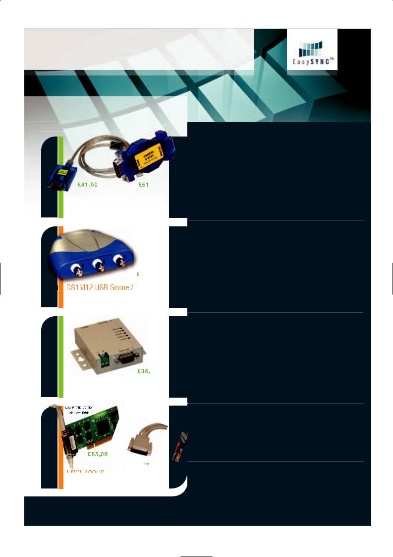
&$1 86% &$1
DIIRUGDEOH &$1 %XV WR 86% DQG 56 LQWHUIDFH VROXWLRQV
%URQ]H 3UL]H :LQQHU 1$6$ 7HFK %ULHIV 3URGXFWV RI WKH <HDU
[ 06 V ,QSXW &KDQQHOV ZDYHIRUP JHQHUDWRU RXWSXW (DV\6FRSH (DV\/RJJHU V Z LQFOXGHG
86% &20 0
3RUW ,QGXVWULDO 86% 56 6HULDO ZLWK ZDOO PRXQW EUDFNHW DQG '& DX[LOLDU\ RXWSXW
83&, +6
3RUW 83&, 56 6HULDO &DUG ZLWK 6SLGHU &DEOH RU &20%2; ,2 H[WUD
$IIRUGDEOH &$1 %XV 6ROXWLRQV
&$186% LV D YHU\ VPDOO GRQJOH WKDW SOXJV LQWR DQ\ 3& 86% 3RUW DQG JLYHV DQ LQVWDQW &$1 FRQQHFWLYLW\ 7KLV PHDQV LW FDQ EH WUHDWHG E\ VRIWZDUH DV D VWDQGDUG &20 3RUW VHULDO 56 SRUW ZKLFK HOLPLQDWHV WKH QHHG IRU DQ\ H[WUD GULYHUV RU E\ LQVWDOOLQJ D GLUHFW GULYHU '// IRU IDVWHU FRPPXQLFDWLRQV DQG KLJKHU &$1 EXV ORDGV &$1 LV D YHU\ VPDOO GRQJOH WKDW SOXJV LQWR DQ\ 3& &20 3RUW RU DQ\ RWKHU 56 SRUW LQ DQ HPEHGGHG V\VWHP DQG JLYHV DQ LQVWDQW &$1 FRQQHFWLYLW\ 7KLV PHDQV LW FDQ EH WUHDWHG E\ VRIWZDUH DV D VWDQGDUG &20 3RUW VHULDO 56 SRUW ZKLFK HOLPLQDWHV WKH QHHG IRU DQ\ H[WUD GULYHUV 6HQGLQJ DQG UHFHLYLQJ FDQ EH GRQH LQ VWDQGDUG $6&,, IRUPDW
SULFHG IURP &$1
86% ,QVWUXPHQWV 3& 2VFLOORVFRSHV /RJLF $QDO\]HUV
2XU UDQJH RI 3& ,QVWUXPHQWV PD\ EH EXGJHW SULFHG EXW KDYH D ZHDOWK RI IHDWXUHV QRUPDOO\ RQO\ IRXQG LQ PRUH H[SHQVLYH LQVWUXPHQWDWLRQ 2XU '6 0 DQG 36 0 RVFLOORVFRSHV KDYH VRSKLVWLFDWHG GLJLWDO WULJJHULQJ LQFOXGLQJ GHOD\HG WLPHEDVH DQG FRPH ZLWK RXU (DV\6FRSH RVFLOORVFRSH VSHFWUXP DQDO\]HU YROWDJH DQG IUHTXHQF\ GLVSOD\ DSSOLFDWLRQ VRIWZDUH DQG RXU (DV\/RJJHU GDWD ORJJLQJ VRIWZDUH :H DOVR SURYLGH :LQGRZV '//V DQG FRGH H[DPSOHV IRU UG SDUW\ VRIWZDUH LQWHUIDFLQJ WR RXU VFRSHV 2XU $17 DQG $17 /RJLF $QDO\]HUV IHDWXUH FDSWXUH FKDQQHOV RI GDWD DW D EOD]LQJ 06 6 VDPSOH UDWH LQ D FRPSDFW HQFORVXUH
SULFHG IURP '6 0 $17
WR SRUW 86% WR 6HULDO $GDSWHUV
:LWK RYHU GLIIHUHQW PRGHOV DYDLODEOH ZH SUREDEO\ VWRFN WKH ZLGHVW UDQJH RI 86% 6HULDO $GDSWHUV DYDLODEOH DQ\ZKHUH :H RIIHU FRQYHUWHU FDEOHV PXOWL SRUW HQFORVXUH VW\OH PRGHOV LQ PHWDO DQG SODVWLF DOVR UDFN PRXQW XQLWV ZLWK LQWHJUDO 368 VXFK DV WKH 86%&20 50 6HULDO LQWHUIDFHV VXSSRUWHG LQFOXGH 56 56 DQG 56 :H DOVR VXSSO\ RSWR LVRODWHG 56 DQG 56 YHUVLRQV IRU UHODLEOH ORQJ GLVWDQFH FRPPXQLFDWLRQV $OO RXU 86% 6HULDO SURGXFWV DUH EDVHG RQ WKH SUHPLXP FKLSVHWV DQG GULYHUV IURP )7', &KLS IRU VXSHULRU FRPSDWLELOLW\ SHUIRUPDQFH DQG WHFKQLFDO VXSSRUW DFURVV :LQGRZV 0$& 26 &( DQG /LQX[ SODWIRUPV
SULFHG IURP 86 % /&
83&, 6HULDO &DUGV
'LVFRYHU RXU JUHDW YDOXH IRU PRQH\ UDQJH RI PXOWL SRUW 83&, VHULDO FDUGV 6XSSRUWLQJ IURP WZR WR HLJKW SRUWV WKH UDQJH LQFOXGHV 56 56 56 DQG RSWR LVRODWHG YHUVLRQV 2XU SRUW DQG SRUW PRGHOV FDQ FRQQHFW WKURXJK H[WHUQDO FDEOHV RU WKH LQQRYDWLYH ZDOO PRXQWLQJ &20%2;
SULFHG IURP 83&, /
(DV\6\QF /WG
6FRWODQG 6WUHHW *ODVJRZ * 4% 8 . 7HO )D[ :HE KWWS ZZZ HDV\V\QF FR XN ( 0DLO VDOHV#HDV\V\QF FR XN
3ULFHV VKRZQ H[FOXGH FDUULDJH DQG 9$7 ZKHUH DSSOLFDEOH
7
INFO & MARKET MAILBOX
Rejektor
Under this heading we will occasionally publish circuits, ideas and suggestions that did not make it to full publication in this magazine for various reasons (like lack of space).
Photoelectrical Oscillator
This circuit of a photoelectrical oscillator (PEO) sent to us by Marcus Bindhammer is an example of an original design approach. Although we’re actually looking at a variant of the astable multivibrator, remarkably there are no capacitors in the circuit. The time constant is not determined by a resistorcapacitor combination as would be expected but by resistance alone. The resistance is formed by a light dependent resistor (LDR) rather than a normal resistor or potentiometer. Oscillation, then, is obtained from the time constant exhibited by an LDR. Marcus described the function as follows.
The PEO works without any kind of quartz crystal, R-C or L-C network. This oscillator is entirely resistance dependent, employing the slowness of light dependent resistors. Particularly with a fast reduction of the ambient light intensity, the ohmic resistance of an LDR will rise relatively slowly. Values for Dt of up to one second have been observed.
The LDR presents a non-linear semiconductor resistance. It is usually made from cadmium-sulphide applied as thin, meandering track on an isolating carrier and electrically connected between two copper electrodes. In response to incident light, electrons are released from molecules. As you will be able to imagine, photons will destroy crystal junctions, causing the number of free electrons and ‘hole’ to increase. The resultant increase in charge carriers causes the relative conductivity to increase.
If the supply voltage is applied to the circuit, the output of the first NAND gate, IC1.A (configured as an inverter) swings logic High (+5 V). This causes LED 1 to light and T1 to conduct. Next, the output of iC1.B goes High, LED2 lights and T2 starts to conduct. Next, the output of IC1.Cgoes High while that of IC1.A goes Low. However, T1 still conducts (due to the slow response of LDR1). When T1 switches off after Dt, or the High level for IC1.B is reached, its output switches to Low (–5 V) and LED2 goes out. T2, too, conducts for a period Dt. When the High level is reached at the input of the third inverter, its output drops
|
IC1.A |
1 |
|
12 |
IC1.D |
|
|
3 |
& |
|
IC1 = 4011 |
|
|
& |
11 |
2 |
13 |
|
|||||
|
|
|
|||||
|
|
|
|
|
|
|
|
R1 |
|
|
R2 |
|
|
||
220 Ω |
|
220 Ω |
|
|
|||
+5V
LED1 |
LDR1 |
R5 |
LED2 |
LDR2 |
R6 |
|
|
|
|
|
16 |
|
|
|
|
|
|
|
|
|
|
|
|
||||||
|
|
100k |
|
|
100k |
|
|
|
15 |
CT=0 |
DEC |
1 |
2 |
|
|
|
|
|
|
|
|
|
|
|
CTRDIV10/ |
0 |
3 |
|
|
|
|
|
|
|
|
|
|
|
|
|
|
|||
|
|
|
|
|
|
5 |
IC1.B |
|
|
|
IC2 |
2 |
4 |
|
|
|
|
|
|
|
|
|
14 |
|
|
|
|||
|
|
|
|
|
|
6 |
& |
4 |
& + |
|
3 |
7 |
|
|
|
|
|
|
|
|
|
R8 |
|
10 |
|
||||
|
|
|
|
|
|
|
|
|
100k |
|
|
4 |
1 |
|
|
R3 |
|
|
R4 |
|
|
IC1.C |
|
|
|
5 |
|
||
|
|
|
|
8 |
|
4017 |
6 |
5 |
|
|||||
|
1k8 |
|
|
1k8 |
|
9 |
& |
10 |
13 |
7 |
6 |
|
||
|
|
|
|
|
|
|
|
|
|
|
|
8 |
9 |
|
|
|
T1 |
|
|
T2 |
|
|
|
|
|
|
9 |
11 |
f |
|
|
|
|
|
|
|
|
|
|
|
CT≥5 |
12 |
|
|
|
|
|
|
|
|
|
|
|
|
|
|
R9 |
||
|
|
BC |
|
|
BC |
|
|
|
|
|
|
|
|
|
|
|
|
|
|
|
|
|
|
|
|
|
Ω |
||
|
P1 |
547B |
|
P2 |
547B |
R7 |
|
|
|
|
8 |
|
|
220 |
100k |
1M |
100k |
LED3 |
|
|||
|
|
|
050132 - 11 |
Low and the output of IC1.A, swings High. This means the circuit has returned to the initial state, and the cycle recommences With the component values shown, an oscillation frequency between about 5 Hz and 50 Hz is obtained, which is adjustable with preset P2. Preset P1 enables fine adjustment, if necessary, and may be replaced by a 100-kΩ
fixed resistor. The 4017 driven by the oscillator divides the quency by 10. With some experimentation and patience the oscillator may be adjusted for the LED at the output to flash at a one-second rate, that is, 1 Hz.
LED1, LED2 |
LDR1, LDR2 |
aluminium tube
black cardboard |
epoxy glue |
LED1, LED2, LED3 = low current, red |
|
LDR1, LDR2 = 1k ... 40k |
050132 - 12 |
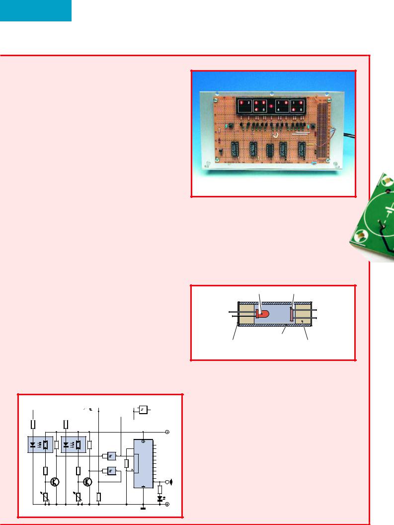
Because LEDs produce heat and LDRs are temperature-depend- ent, the LDR-LED pairs are mounted in sealed aluminium tubes in order to aid their dissipation. A suggested construction of the LED/LDR optocoupler is illustrated in the second drawing. The author’s photoelectrical oscillator is functional in a digital clock. As shown by the photograph of time readout, the clock is as unusual as the PEO, the time being indicated in binary format! For the sake of legibility however the display was designed to show hours and minutes as tens and units, just as on a regular clock. If you are interested in the design of the complete clock, the author’s complete description of it including circuit diagrams and the display artwork is available as a free download from the Elektor Electronics website at www.elektor-electronics.co.uk, under Magazine, January 2006, Mailbox. The information is presented ‘as is’.
Finally, we should mention that there is as yet no indication of the long-term stability of the PEO. It is however safe to assume that the accuracy of the PEO clock is about the same as that of a mechanical alarm clock. If you need better accuracy, go for a quartz crystal oscillator or divide the 50-Hz mains down to 1 Hz to drive the clock.
8 |
elektor electronics - 1/2006 |
Wrong diode
Dear Editor — in your article ‘Slave Flash with Red-Eye Reduction’ (July/August 2005) I found sensor diode D1 labelled as a type TLRH180P. Having looked up the device specifications, I noticed that this is just an ordinary (albeit red) diode, is it correct?
Jeremy Deakin (UK)
It is not, sorry for the misprint. D1 may be a BPW40 phototransistor, with its collector (at the bevelled edge of the enclosure) con-
RF wattmeter
Dear Sir — a few days ago I sent you an email in which I described a problem with the Menu button in the RF Wattmeter (October 2002).
The button simply does not what it’s supposed to do. In the mean time I managed to find the solution. In the hex file on your website (and that of the author, OZ2CPU), address 2007h (configuration word) reads 3375h. Consequently bit 11 is set, causing the background debugger to be enabled. However, pin 27 (Menu but-
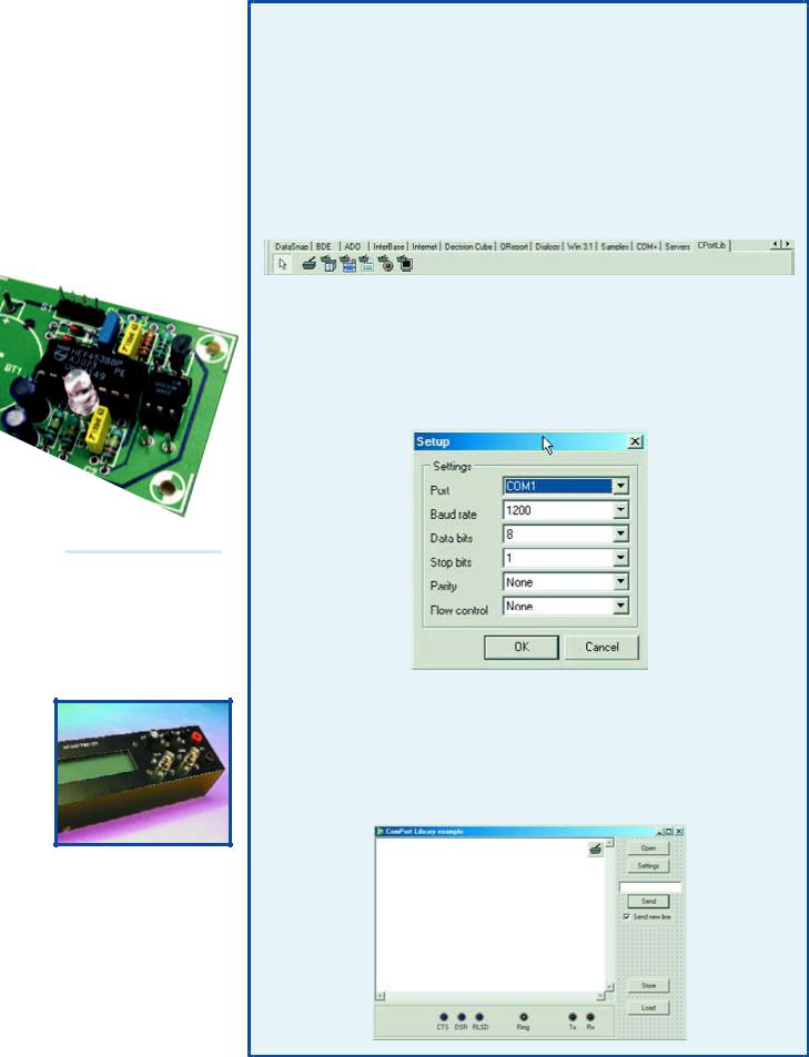
RS232 component for Delphi 3-7
Dear Editor — I really |
extended with CPortLib |
• ComPort WriteStr(Str) for |
enjoyed reading the Delphi |
which in turn contains com- |
|
for Electronic Engineers |
ponents |
transmission of data (Str for |
course (published over the |
Comport, ComDataPacket, |
String); |
previous ten issues, Ed.). |
ComComboBox, |
• ComPort.ReadStr(Str, |
However I noticed that lots |
ComRadioGroup, Comled |
|
of hobbyists still run into |
and ComTerminal. See |
Count) for receiving data (Str |
problems if they want to |
Figure 1. |
for string, Count is an inte- |
control a simple electronic |
|
ger; Count indicates the num- |
circuit on the RS232 (COM) |
Comport is the essential |
ber characters read into Str). |
|
|
|
|
|
|
|
1 |
|
||
port, using a program to be |
component, requiring only |
There’s also a procedure |
||||||||
written by themselves. For |
|
a few modules to be |
called |
|||||||
quite some time now, I’ve |
|
added to make up a com- |
ComPort.ShowSetupDialog |
|||||||
been using a ‘component’ |
|
munications program for |
(Figure 2) which pops up a |
|||||||
that’s freely downloadable |
|
transmission and reception |
dialogue window allowing |
|||||||
from the Internet. This com- |
|
of information. |
users to configure a number |
|||||||
ponent, it seems to me, |
|
|
of settings like port, bau- |
|||||||
makes an excellent |
|
|
|
|
|
drate, number of data |
||||
add-on to the course. |
|
|
|
|
bits, parity and flow |
|||||
Very easy to use, it is |
|
|
|
|
control. This, by the |
|||||
compatible with Delphi |
|
|
|
|
way, is also possible |
|||||
versions 3 through 7. |
|
|
|
|
with the component’s |
|||||
Mr Dejan Crnila’s |
|
|
|
|
|
Properties. |
||||
highly interesting |
|
|
|
|
|
Comled is another |
||||
ComPort Library may |
|
|
|
|
interesting component. |
|||||
be found at |
|
|
|
|
|
It allows activity on |
||||
http://sourceforge. |
|
|
|
|
|
the CTS, DSR, RLSD, |
||||
net/projects/comport. |
|
|
|
|
Tx and Rx lines to be |
|||||
|
|
|
|
|
|
|
|
visualised. |
||
It allows a program to |
|
|
|
|
||||||
be written for easy |
|
|
|
|
|
Figure 3 shows the |
||||
communication with |
|
|
|
|
|
|||||
equipment or an elec- |
|
2 |
|
|
example called |
|||||
tronic device via the |
|
|
|
|
ComExample, which |
|||||
serial port. The zip file |
|
|
|
|
is supplied complete |
|||||
cport3.0.zip contains two |
|
|
with its source code listing |
|||||||
folders: Source and |
|
|
|
The essential procedures |
and a number of other |
|||||
Example. The latter holds a |
|
include: |
examples. |
|||||||
number of examples like a |
|
|
It took me less than half an |
|||||||
ComPort Library and Mini |
|
• Comport.Open and |
hour to control and read a |
|||||||
Terminal, all with full source |
ComPort.Close with their |
Fluke 45 multimeter using |
||||||||
code files supplied. There’s |
|
obvious functions; |
my PC. A similar program |
|||||||
also a readme |
|
|
|
|
|
|
for EEDTs |
|||
text file giving |
|
|
|
|
|
|
|
model train, |
||
|
|
|
|
|
|
|
||||
details on the |
|
|
|
|
|
|
|
semaphore and |
||
installation of |
|
|
|
|
|
|
|
points control |
||
the various |
|
|
|
|
|
|
|
should be with- |
||
components. I |
|
|
|
|
|
|
|
in easy reach. |
||
would heartily |
|
|
|
|
|
|
|
All in all, an |
||
recommend |
|
|
|
|
|
|
|
|||
reading this |
|
|
|
|
|
|
|
interesting com- |
||
file. Once |
|
|
|
|
|
|
|
ponent to |
||
you’ve installed |
|
|
|
|
|
|
|
experiment |
||
the files in the |
|
|
|
|
|
|
|
with. |
||
right locations, |
|
|
|
|
|
|
|
|
|
|
the Component |
|
3 |
|
|
|
|
|
H. Jorissen |
||
Palette is |
|
|
|
|
|
|
(Netherlands) |
|||
1/2006 - elektor electronics |
9 |
INFO & MARKET MAILBOX
ton), is then erroneously assigned to debugging instead of controlling the menu.
Proposed solution:
Change address 2007 to 3F75h and the problems are over (bit 10 is also set, but it is not implemented, see datasheet).
p.s. I am using the Galep programmer so I do not have a menu to define the PIC configuration word.
Robin Beaman (UK)
Thanks for the tip Robin.
Replacement for BD911/912
Dear Jan — are you aware of direct replacements for the BD911 and BD912 transistors originally used for the 1990 PowerAmp in your magazine? My suppliers tell me these transistors are no longer available.
A van Niele (Netherlands)
As far as we know the BD911 and BD912 are still being produced. They may be obtained from, among others, Schuricht in Germany (www.schuricht.com)
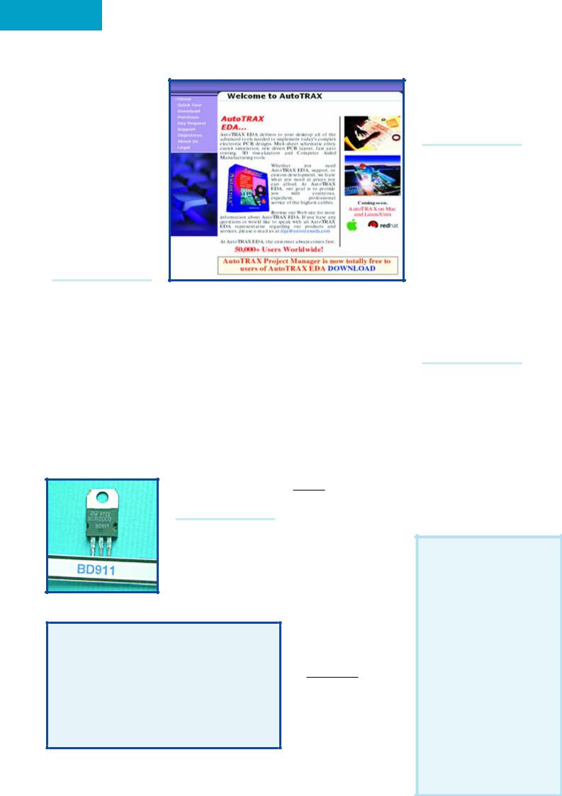
Free electronic CAD tools DVD (1)
Dear Jan — what a terrific idea to enclose a free DVD with your November 2005 issue. I did however miss one program (or hyperlink): Autotrax EDA (currently at version 7.2) by Ilja Kovacevic. The program suite may be downloaded from www.autotraxeda.com and requires about 40 MBytes on the hard disk.
Franz Hrubes (Germany)
Thanks for the pointer, in the hectic of compiling and producing the DVD Autrotrax was somehow overlooked, our apologies.
Free electronic CAD tools DVD (2)
Dear Editor — I received the November issue yesterday, and I found the article on electronic CAD tools very
Corrections & Updates
ESR/C Meter
September 2005, p. 30, 040259-1.
Resistor R10 is shown as 1 kΩ in the circuit diagram and 10 kΩ in the parts list. The latter value is correct, although not critical in this application.
Readers are advised that an FAQ on the ESR/C Meter is available in our online Forum.
interesting. I would like to add a comment though. One aim of the article is claimed to be to guide the average I-need-to-do-a-small-
PCB-in-an-hour hobbyist to the most suitable tool.
Well, if this is indeed the case then I think an important option has been left out: The DOS version of Protel’s Schedit and Autotrax tools. These tools are now ‘aban- don-ware’ and can be downloaded as such free of charge from Protel’s website. www.altium.com/Community /Support/Downloads/
(look for “Freeware Downloads”)
An electronics company in Australia appears to be using these tools, and among other things they have offered to the public domain hi-res Vesa drivers, an updated footprint library for Autotrax, and a “print-to-PCX” printer driver.
www.airborn.com.au/ layout/easytrax.html
www.airborn.com.au/ layout/autolib1.html
www.airborn.com.au/ layout/printdrv.html
From a strictly professional point of view these program might be obsolete, but they are still perfectly suitable for getting a small design done in a jiffy. I use them myself as
10
a hobbyist and I can only recommend them.
Klaus Klug Christiansen
Nice to hear from yu again
Podcast converter
Dear Editor — as someone who does not have a PC at home, I was wondering if you were considering a dedicated unit to enable analogue audio to be converted to a format suitable for down loading into i-pods etc.?
I have been reading Elektor since the 1970s; always interesting and informative. Keep up the good work!
Howard Thompson
Thanks for the suggestion Howard, we will study the feasibility.
Mind the GAP
Dear Jan — tube lovers like myself revelled at the photograph of the GAP/R tube opamp device at the start of your article on opamp selection criteria (November 2005). Those who want to know more should have a look at the archive of ‘AnalogDialogue’ e- zine at www.analog.com, look for ‘GAP/R’.
Roy Marks (UK)
MailBox Terms
– Publication of reader’s correspondence is at the discretion of the Editor.
– Viewpoints expressed by correspondents are not necessarily those of the Editor or Publisher.
– Correspondence may be translated or edited for length, clarity and style.
– When replying to Mailbox correspondence, please quote Issue number.
– Please send your MailBox correspondence to:
editor@elektor-electronics.co.uk or Elektor Electronics, The Editor, P.O.
Box 190,
Tunbridge Wells TN5 7WY, England.
elektor electronics - 1/2006