

General electric VAT2000
.pdf6. Control Functions and Parameter Settings
6-7-2 Speed regulator (IM)
The speed regulator (ASR) is configured of PI control, and has the following parameters.
Parameter |
Parameter |
Function |
No. |
|
|
A10-0 |
ASR response |
Set the required ASR response in radians |
A10-1 |
Machine time constant1 |
Set the time to accelerate the motor and load to the base |
|
|
speed at the rated motor torque. |
A10-2 |
Integral time constant |
Set the compensation coefficient applied on the integral time |
|
compensation coefficient |
constant of the speed regulator (ASR). |
B13-6 |
ASR gain compensation in |
This sets the ASR P gain compensation value at the max. |
|
constant power range |
speed. |
|
|
By adjusting this parameter, the ASR P can be compensated |
|
|
in the constant power range. |
|
|
If ASR hunting occurs in the sensor-less control's constant |
|
|
output range, set a smaller value. |
B30-2 |
ASR proportional change |
This limit the ASR's Proportional block, if the speed setting |
|
rate limit |
value or motor speed change suddenly,. |
6-7-3 Motor Torque limit (IM)
The output torque is limited. Set an appropriate value for protecting the load side.
Drive torque limit) |
Set this to a large value to increase the torque during driving. Note that the |
|||
|
|
|
output torque is limited by the output current limit (B18-0), so when set |
|
|
|
|
excessively, the set torque may not be attained. |
|
Regenerative torque limit) |
Set this to a large value to increase the torque during regeneration. Note |
|||
|
|
|
that the output torque is limited by the output current limit (B18-0), so when |
|
|
|
|
set excessively, the set torque may not be attained. If the DBR or PWM |
|
|
|
|
converter, etc., are not provided and an excessively large setting is made, |
|
|
|
|
an overvoltage trip could occur during regeneration. In this case, lower the |
|
|
|
|
regeneration torque limit setting. |
|
|
|
|
|
|
|
Parameter |
Parameter |
Function |
|
|
No. |
|
|
|
|
A10-3 |
ASR drive torque limit |
Drive torque limit in ASR control. |
|
|
A10-4 |
ASR regenerative torque |
Regenerative torque limit in ASR control. |
|
|
|
limit |
|
|
|
A10-5 |
Emergency stop |
Regenerative torque limit value for emergency stop in ASR |
|
|
|
regenerative torque limit |
Control. |
|
|
A11-2 |
ACR drive torque limit |
Drive torque limit in ACR control. |
|
|
A11-3 |
ACR regenerative torque |
Regenerative torque limit in ACR control. |
|
|
|
limit |
|
|
6-76
6. Control Functions and Parameter Settings
6-7-4 Exciting current control
The exciting current is controlled to establish the secondary flux. A current reduction process in the constant output range or during voltage saturation, and high-speed magnetising control to raise the secondary flux at a high speed are also carried out.
Parameter |
Parameter |
Function |
No. |
|
|
B32-0 |
Speed flux control |
This is the control selection for magnetising the |
|
selection |
secondary flux to a high speed when starting operation. |
|
|
Select this to increase the motor speed even slightly |
|
|
when starting operation. |
B32-2 |
Voltage saturation |
If the output voltage in control is larger than the voltage |
|
compensation selection |
that can be output by the inverter, select this control to |
|
|
limit the exciting current to prevent the current or torque |
|
|
from hunting. |
|
|
Select this when raising the output voltage to near the |
|
|
input voltage, or when the input voltage changes. |
|
|
Note that if voltage saturation occurs, some torque ripple |
|
|
will occur. In this case, lower the B01-9 no-load voltage |
|
|
setting to avoid voltage saturation. |
B33-x |
Table reference speed |
This is the reference speed for changing the |
|
|
compensation amount according to the operation speed. |
|
|
Set as shown below to operate to the constant output |
|
|
range. |
B34-x |
M fluctuation |
This compensates the exciting inductance fluctuation |
|
compensation |
according to the B33 table reference speed. |
|
|
Set the compensation table so that the output voltage is |
|
|
constant during no-load operation through the entire |
|
|
operation range. |
|
|
* This is adjusted by the automatic tuning mode 4. (B19- |
|
|
0) |
|
|
|
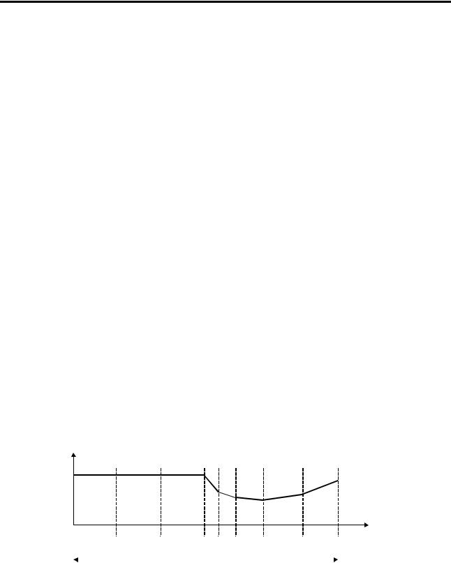
<Setting the table reference speed>
M' fluctuations greatly immediately after entering the constant output range, so set using the following diagram as a reference. (The base speed is 1.)
M' fluctuation coefficient 100%
speed
0.3 |
0.6 |
1 |
1.1 |
1.2 |
1.4 |
1.7 |
2 |
O peration range
Setting the reference speed table
6-77

6. Control Functions and Parameter Settings
6-7-5 Current regulator (IM)
The current regulator (ACR) is a PI type control, including the following parameters.
Parameter |
Parameter |
Function |
No. |
|
|
A11-0 |
ACR response |
Set the ACR response in radians. |
|
|
If the response is too low or too high, the current will become |
|
|
unstable, and the over current protection will function. |
A11-1 |
ACR time constant |
The ACR time constant is set. |
|
|
If the time constant is too long or too short, the current will |
|
|
become unstable, and the over current protection will |
|
|
function. |
B13-7 |
ACR gain compensation in |
This sets the ACR Proportional gain compensation value at |
|
constant power range |
the max. speed. (above base speed) |
B32-4 |
ACR voltage model FF |
The voltage fluctuation caused by the leakage inductance is |
|
selection |
feed forward controlled. |
|
|
The current regulator (ACR) response speed will be |
|
|
increased. Select this if the current hunts in the high-speed |
|
|
operation range during sensor-less control. |
6-7-6 Flux observer and speed estimation mechanism (IM)
These are parameters used with speed sensor-less vector control.
Parameter |
Parameter |
Function |
No. |
|
|
|
|
|
B31-0 |
Flux observer gain |
This is the feedback gain for the flux observer. |
|
|
If hunting occurs at the estimated speed in the high-speed |
|
|
operation range, adjust within the range of 1.2 to 0.9. |
B31-1 |
Speed estimated |
This is the proportional gain for the adaptive speed |
|
proportional gain |
estimation mechanism. To increase the speed estimation |
|
|
response, set a large value. Note that if the value is too high, |
|
|
the speed estimation value will hunt. |
B31-2 |
Speed estimated integral |
This is the integral gain for the adaptive speed estimation |
|
gain |
mechanism. To increase the speed estimation response, set |
|
|
a large value. Note that if the value is too high, the speed |
|
|
estimation value will hunt. |
6-78

6. Control Functions and Parameter Settings
6-7-7 Load torque observer (IM)
The disturbance load applied on the motor is calculated and the torque command is compensated. To increase the response toward disturbance, use the load torque observer.
By setting the speed regulator (ASR) to P and using the load torque observer, overshooting can be suppressed.
Parameter |
Parameter |
Function |
No. |
|
|
|
|
|
B30-0 |
Load torque observer gain |
Set the observer gain for the load torque observer. |
|
|
To increase the responsiveness of the external disturbance |
|
|
response characteristics, set a large gain. |
|
|
Note that if the gain is set too high, the output torque could |
|
|
hunt. |
|
|
When set to zero, the load torque observer will not function. |
|
|
|
B30-1 |
Model machine time |
Set the model machine time constant used by the load |
|
constant |
torque observer. |
6-7-8 Various low path filters (IM)
The time constants of the low path filters used for speed detection, speed commands or torque current commands, etc., are set.
By adjusting these time constants, vibration caused by noise and overshooting can be suppressed. Note that if an excessively high value is set, the control performance could drop.
Parameter |
Parameter |
Function |
No. |
|
|
|
|
|
B30-3 |
Speed setting LPF time |
Overshooting can be suppressed by setting this to the filter |
|
constant |
time constant equivalent to the speed response. |
B30-4 |
Speed detection LPF time |
The speed detection noise is cut. |
|
constant |
|
B30-5 |
Speed detection LPF time |
Set the low path filter time constant used for the speed |
|
constant for ASR |
detection value input into the speed regulator. |
B30-6 |
Speed detection LPF time |
Set the low path filter time constant used for the speed |
|
constant for compensation |
detection value for constant output range compensation or |
|
|
iron loss compensation, etc. |
B30-7 |
Torque current command |
Set the low path filter time constant used for the torque |
|
setting LPF time constant |
current command. |
6-79
7. Options
Chapter 7 Options
7-1 Outline of options
The VAT2000 Series include the options shown below. This chapter will focus on the stand-alone options and main circuit wiring devices.
|
|
|
|
|
|
|
|
|
|
|
|
|
|
|
|
|
|
|
|
|
|
|
|
|
|
|
|
|
|
|
|
|
|
|
|
|
|
|
|
|
|
|
|
|
|
|
|
|
|
|
|
|
|
|
|
|
|
|
|
|
|
|
|
|
|
|
|
|
|
|
|
|
|
|
|
|
|
|
|
|
|
|
|
|
|
|
|
|
|
|
|
|
|
|
|
|
|
Stand-Alone option |
|
|
|
|
|
|
|
|
|
|
|
|
|
|
|
DCL |
|
|
|
|
|
|
|
|
|
|
|
||||||||||||||||||||||||||||||||||||||||||||||||||||
|
|
|
|
|
|
|
|
|
|
|
|
|
|
|
|
|
|
|
|
|
|
|
|
|
|
|
|
|
|
|
|
|
|
|
|
|
|
|
|
|
|
|
|
|
|
|
|
|
|
|
|
|
|
|
|
|
|
|
|
|
|
|
|
|
|
|
|
|
|
|
|
|
|
|
|
|
|
|
|
|
|
|
|
|
|
|
|
|
|
|
|
|
|
|
|
|
|
|
|
|
|
|
|
|
|
|
|
|
|
|
|
|
|
|
|
|
|
|
|
|
|
|
|
|
|
|
|
|
|
|
|
|
|
|
|
|
|
|
|
|
|
|
|
|
|
|
|
|
|
|
|
|
|
|
|
|
|
|
|
|
|
|
|
|
|
|
|
|
|
|
|
|
|
|
|
|
|
|
|
|
|
|
|
|
|
|
|
|
|
|
|
|
|
|
|
|
|
|
|
|
|
|
|
|
|
|
|
|
|
|
|
|
|
|
|
|
|
|
|
|
|
|
|
|
|
|
|
|
|
|
|
|
|
|
|
|
|
|
|
|
|
|
|
|
|
|
|
|
|
|
|
|
|
|
|
|
|
|
|
|
|
|
|
|
|
|
|
|
|
|
|
|
|
|
|
|
|
|
|
|
|
|
|
|
|
|
|
|
|
|
|
|
|
|
|
|
|
|
|
|
|
|
|
|
|
|
|
|
|
|
|
|
|
|
|
|
|
|
|
|
|
|
|
|
|
|
|
|
|
|
|
|
|
|
|
|
|
|
|
|
|
|
|
|
|
|
|
|
|
|
|
|
|
|
|
DBR Unit
Main circuit wiring device
Power Supply |
|
|
|
|
|
|
|
|
|
|
|
|
|
|
|
|
|
|
|
|
|
|
|
Noise Filter |
VAT2000 |
||
|
|
MCCB or |
|
|
|
|
|
|
|
|
|||||||||||||||||
|
|
|
|
|
|
|
|
|
|
|
|
|
ACL |
|
|
||||||||||||
|
|
|
|
|
fuse |
|
|
|
MC |
|
|
|
|
|
|
|
|
||||||||||
|
|
|
|
|
|
|
|
|
|
|
|
|
|
|
|
|
|
|
|
|
|
|
|
|
|
|
|
M
|
|
|
|
|
|
|
|
|
|
|
|
|
|
|
|
|
|
|
|
|
|
|
|
|
|
|
|
|
|
|
|
|
|
|
|
|
|
|
|
|
|
|
|
|
|
|
|
|
|
|
|
|
|
|
|
|
|
|
|
|
|
|
|
|
|
|
|
|
|
|
|
|
|
|
|
|
|
|
|
|
|
|
|
|
|
|
|
|
|
|
|
|
|
|
|
|
|
|
|
|
|
|
|
|
|
|
|
|
|
|
|
|
|
|
|
|
|
|
|
|
|
|
|
|
|
|
|
|
|
|
|
|
|
|
|
|
|
|
|
|
|
|
|
|
|
|
|
|
|
|
|
|
|
|
|
|
|
|
|
|
|
|
|
|
|
|
|
|
|
|
|
|
|
|
|
|
|
|
|
|
|
|
|
|
|
|
|
|
|
|
|
|
|
|
|
|
|
|
|
|
|
|
|
|
|
|
|
|
|
|
|
|
|
|
|
|
|
|
|
|
|
|
|
|
|
|
|
|
|
|
|
|
|
|
|
|
|
|
|
|
|
|
|
|
|
|
|
|
|
|
|
|
|
|
|
|
|
|
|
|
|
|
|
|
|
|
|
|
|
|
|
|
|
|
|
|
|
|
|
|
|
|
|
|
|
|
|
|
|
|
|
|
|
|
|
|
|
|
|
|
|
|
|
|
|
|
|
|
|
|
|
|
|
|
|
|
|
|
|
|
|
|
|
|
|
|
|
|
|
|
|
|
|
|
|
|
|
|
|
|
|
|
|
|
|
|
|
|
|
|
|
|
|
|
|
|
|
|
|
|
|
|
|
|
|
|
|
|
|
|
|
|
|
|
|
|
|
|
|
|
|
|
|
|
|
|
|
|
|
|
|
|
|
|
|
|
|
|
|
|
|
|
|
|
|
|
|
|
|
|
|
|
|
|
|
|
|
|
|
|
|
|
|
|
|
|
|
|
|
|
|
|
|
|
|
|
|
|
|
|
|
|
|
|
|
|
|
|
|
|
|
|
|
|
|
|
|
|
|
|
|
|
|
|
|
|
|
|
|
|
|
|
|
|
|
|
|
|
|
|
|
|
|
|
|
|
|
|
|
|
|
|
|
|
|
|
|
|
|
|
|
|
|
|
|
|
|
|
|
|
|
|
|
|
|
|
|
|
|
|
|
|
|
|
|
|
|
|
|
|
|
|
|
|
|
|
|
|
|
|
|
|
|
|
Built-in PCB option |
||||||
|
|
|
|
|
|
|
|
|
|
|
|
|
|
|
|
|
|
|
|
|
|
|
|
|
|
|
|
|
|
|
|
Fig. 7-1 Option configurations |
||||||||||||||||||||||||||||||||||||
|
|
|
|
|
|
|
|
|
|
|
|
|
|
|
|
|
|
|
|
|
|
|
|
|
|
|
|
|
|
|
|
|
|
|
|
|
|
|
|
|
|
|
|
|
|
|
Table 7-1 |
|||||||||||||||||||||
|
|
|
|
|
|
|
|
|
|
|
|
|
|
|
|
|
|
|
|
|
|
|
|
|
|
|
|
|
|
|
|
|
|
|
|
|
|
|
||||||||||||||||||||||||||||||
|
Item |
|
|
|
|
|
|
|
|
|
|
|
Type |
|
|
|
|
|
|
|
|
|
|
|
|
|
|
|
|
|
|
|
|
|
|
|
|
Function |
||||||||||||||||||||||||||||||
|
|
|
|
|
|
|
|
|
|
|
|
|
|
|
|
|
|
|
|
|
|
|
|
|
|
|
|
|
|
|
|
|
|
|||||||||||||||||||||||||||||||||||
Main circuit wiring devices |
|
|
|
|
|
|
|
|
|
|
|
|
|
|
|
|
|
|
|
|
|
|
|
|
|
|
|
|
|
|
|
|||||||||||||||||||||||||||||||||||||
|
|
|
|
|
|
|||||||||||||||||||||||||||||||||||||||||||||||||||||||||||||||
|
Breaker for |
|
Select a device that |
|
Always install this device to protect the wiring of the inverter |
|||||||||||||||||||||||||||||||||||||||||||||||||||||||||||||||
|
wiring (MCCB) |
|
matches the inverter |
|
and peripheral devices. |
|||||||||||||||||||||||||||||||||||||||||||||||||||||||||||||||
|
or Fuse |
|
rating. (Table 7-2.) |
|
|
|
|
|
|
|
|
|
|
|
|
|
|
|
|
|
|
|
|
|
|
|
|
|
|
|
|
|
|
|
||||||||||||||||||||||||||||||||||
|
Magnetic |
|
Select a device that |
|
Install this device to provide an operation interlock. |
|||||||||||||||||||||||||||||||||||||||||||||||||||||||||||||||
|
contactor (MC) |
|
matches the inverter |
|
When using the DBR unit, always install this device to protect |
|||||||||||||||||||||||||||||||||||||||||||||||||||||||||||||||
|
|
|
|
|
|
|
|
|
|
|
rating. (Table 7-2.) |
|
the DBR. (Refer to Fig. 2-4.) |
|||||||||||||||||||||||||||||||||||||||||||||||||||||||
Stand-alone options |
|
|
|
|
|
|
|
|
|
|
|
|
|
|
|
|
|
|
|
|
|
|
|
|
|
|
|
|
|
|
|
|||||||||||||||||||||||||||||||||||||
|
|
|
|
|
|
|||||||||||||||||||||||||||||||||||||||||||||||||||||||||||||||
|
ACL |
|
ACR-• • • • |
|
If the capacity of the inverter's power supply transformer |
|||||||||||||||||||||||||||||||||||||||||||||||||||||||||||||||
|
|
|
|
|
|
|
|
|
|
|
(Refer to Table 7-2.) |
|
exceeds 10 times the inverter unit capacity, always install this |
|||||||||||||||||||||||||||||||||||||||||||||||||||||||
|
|
|
|
|
|
|
|
|
|
|
|
|
|
|
|
|
|
|
|
|
|
|
|
|
|
|
|
|
|
|
|
|
|
|
|
|
|
|
device to protect the inverter. (Balance with power supply) This |
|||||||||||||||||||||||||||||
|
|
|
|
|
|
|
|
|
|
|
|
|
|
|
|
|
|
|
|
|
|
|
|
|
|
|
|
|
|
|
|
|
|
|
|
|
|
|
is also effective in improving the power factor of the inverter |
|||||||||||||||||||||||||||||
|
|
|
|
|
|
|
|
|
|
|
|
|
|
|
|
|
|
|
|
|
|
|
|
|
|
|
|
|
|
|
|
|
|
|
|
|
|
|
input and in suppressing the current high harmonics. The power |
|||||||||||||||||||||||||||||
|
|
|
|
|
|
|
|
|
|
|
|
|
|
|
|
|
|
|
|
|
|
|
|
|
|
|
|
|
|
|
|
|
|
|
|
|
|
|
factor will be approx. 0.9. |
|||||||||||||||||||||||||||||
|
DCL |
|
DCR-• • • • |
|
Install this device to improve the power factor of the inverter |
|||||||||||||||||||||||||||||||||||||||||||||||||||||||||||||||
|
|
|
|
|
|
|
|
|
|
|
(Refer to Table 7-2.) |
|
input. |
|||||||||||||||||||||||||||||||||||||||||||||||||||||||
|
|
|
|
|
|
|
|
|
|
|
|
|
|
|
|
|
|
|
|
|
|
|
|
|
|
|
|
|
|
|
|
|
|
|
|
|
|
|
This is also effective in creating a balance with the power |
|||||||||||||||||||||||||||||
|
|
|
|
|
|
|
|
|
|
|
|
|
|
|
|
|
|
|
|
|
|
|
|
|
|
|
|
|
|
|
|
|
|
|
|
|
|
|
supply as the ACL. The power factor will be approx. 0.9. |
|||||||||||||||||||||||||||||
|
Noise filter |
|
PR-• • • • |
|
This device suppresses the electromagnetic noise generated by |
|||||||||||||||||||||||||||||||||||||||||||||||||||||||||||||||
|
|
|
|
|
|
|
|
|
|
|
(Refer to Table 7-2.) |
|
the inverter. |
|||||||||||||||||||||||||||||||||||||||||||||||||||||||
|
|
|
|
|
|
|
|
|
|
|
|
|
|
|
|
|
|
|
|
|
|
|
|
|
|
|
|
|
|
|
|
|
|
|
|
|
|
|
The electromagnetic noise is the radiation of electromagnetic |
|||||||||||||||||||||||||||||
|
|
|
|
|
|
|
|
|
|
|
|
|
|
|
|
|
|
|
|
|
|
|
|
|
|
|
|
|
|
|
|
|
|
|
|
|
|
|
waves in the radio frequency bands and that conveyed to the |
|||||||||||||||||||||||||||||
|
|
|
|
|
|
|
|
|
|
|
|
|
|
|
|
|
|
|
|
|
|
|
|
|
|
|
|
|
|
|
|
|
|
|
|
|
|
|
power supply wires. Mounting of this device is recommended |
|||||||||||||||||||||||||||||
|
|
|
|
|
|
|
|
|
|
|
|
|
|
|
|
|
|
|
|
|
|
|
|
|
|
|
|
|
|
|
|
|
|
|
|
|
|
|
for creating a balance with the peripheral devices of the |
|||||||||||||||||||||||||||||
|
|
|
|
|
|
|
|
|
|
|
|
|
|
|
|
|
|
|
|
|
|
|
|
|
|
|
|
|
|
|
|
|
|
|
|
|
|
|
inverter. |
|||||||||||||||||||||||||||||
|
DBR unit |
|
U2KV23DBU-• • |
|
This is used when the motor is to be stopped with dynamic |
|||||||||||||||||||||||||||||||||||||||||||||||||||||||||||||||
|
|
|
|
|
|
|
|
|
|
|
(Refer to Table 7-2.) |
|
braking. |
|||||||||||||||||||||||||||||||||||||||||||||||||||||||
|
|
|
|
|
|
|
|
|
|
|
|
|
|
|
|
|
|
|
|
|
|
|
|
|
|
|
|
|
|
|
|
|
|
|
|
|
|
|
|
|
|
|
|
|
|
|
|
|
|
|
|
|
|
|
|
|
|
|
|
|
|
|
|
|
|
|
|
|
7-1

7. Options
Table 7-1 (continued)
Plug-in PCB options
|
Item |
Type |
|
|
Function |
Option |
|
|
& |
|
|
|
class |
|
|
|
|
|
|
|
|
|
Manual |
|
|
|
|
|
|
|
|
|
||
|
Speed detection |
U2KV23DN1 |
This is a speed detection PCB for the IM vector control |
I |
||
|
1 (complimentary |
(PCST-3229) |
with speed sensor, and is compatible with the |
|
||
|
compatible) |
|
complimentary output type encoder. |
|
||
|
|
|
Response frequency: Change between 60±10kHz and |
|
||
|
|
|
20kHz. |
|
|
|
|
Speed detection |
U2KV23DN2 |
This is a speed detection PCB for the IM vector control |
I |
||
|
2 (line driver |
(PCST-3300) |
with speed sensor, and is compatible with the line |
|
||
|
compatible) |
|
driver output type encoder. |
|
||
|
|
|
Response frequency: 250kHz (signal: A, B, Z phase) |
|
||
|
Speed detection |
U2KV23DN3 |
This is a speed detection PCB for the PM drive |
I |
||
|
3 (PM |
(PCST-3301) |
control, and is compatible with the line driver output |
|
||
|
compatible) |
|
type encoder. |
|
|
|
|
|
|
Response frequency: 250kHz (signal: A, B, Z, U, V, W |
|
||
|
|
|
phase) |
|
|
|
|
Relay interface |
U2KV23RY0 |
This is used to expand the contact input/output points. |
III |
||
|
|
(PCST-3302) |
Relay input |
|
: 4 points (PSI6 to 9) |
|
|
|
|
1c contact output |
: 2 points (PSO4, 5) |
|
|
|
PC interface |
U2KV23PI0 |
This is used to receive parallel settings from the PLC. |
III |
||
|
|
(PCST-3303) |
Parallel data input |
: 16 bits |
|
|
|
|
|
Data length |
|
: 16, 12, 8 bits selective |
|
|
|
|
Format |
|
: Binary or BCD selective |
|
|
|
|
Open collector output : 2 points (PSO4, 5) |
|
||
|
Serial interface |
U2KV23SL0 |
This is used to make a connection with serial |
III |
||
|
|
(PCST-3304) |
transmission to the personal computer, etc. |
|
||
|
|
|
Transmission |
|
: RS-232C, RS-422/485Multi- |
|
|
|
|
|
|
drop is possible for up to 32 |
|
|
|
|
|
|
units. |
|
|
|
|
Baud rate |
|
: 1200~9600 bps |
|
|
Profibus interface |
U2KV23SL6 |
This is used to make a connection with the network on |
III |
||
|
|
(PCST-3307) |
the Profibus DP communication protocol. |
|
||
|
|
|
Baud rate |
: 12Mbps |
|
|
|
|
|
No. of stations : 126 stations |
|
||
|
Analog interface |
U2KV23AD0 |
This is used to give the analog setting input a higher |
II |
||
|
(*) |
(PCST-3264) |
precision. |
|
|
|
|
|
|
Analog input |
: 3 points (insulated: signed 15 bits) |
|
|
|
Trace back |
U2KV23TR0 |
This is used to analyse a fault by saving, replaying and |
II |
||
|
interface |
(PCST-3265) |
analysing the various data such as the current at the |
|
||
|
(*) |
|
time of the fault. |
|
|
|
|
|
|
Analog output |
: 2 points (insulated: signed 11 bits) |
|
|
The above Optional PCBs must be installed by the user. Please ask your supplier for dedicated instruction manuals.
(*) Future development
7-2

7. Options
Table 7-2 Main circuit wiring device ratings and stand-alone option types (1) (4)
|
|
|
|
|
|
|
|
|
|
|
|
|
|
|
|
|
|
|
|
|
!" |
!" |
# |
|
|
|
|
|
|
|
|
|
|
|
|
|
|
|
|
|
|
|
|
|
|
|
|
|
|
|
|
|
|
|
|
|
|
|
|
|
|
|
|
|
|
|
|
|
|
|
|
|
|
|
|
|
|
|
|
|
|
|
|
|
|
|
|
|
|
|
|
|
|
|
|
|
|
|
|
|
|
|
|
|
|
|
|
|
|
|
|
|
|
|
|
|
|
|
|
|
|
|
|
|
|
|
|
|
|
|
|
|
|
|
|
|
|
|
|
|
|
|
|
|
|
|
|
|
|
|
|
|
|
|
|
|
|
|
|
|
|
|
|
|
|
|
|
|
|
|
|
|
|
|
|
|
|
|
|
|
|
|
|
|
|
|
|
|
|
|
|
|
|
|
|
|
|
|
|
|
|
|
|
|
|
|
|
|
|
|
|
|
|
|
|
|
|
|
|
|
|
|
|
|
|
|
|
|
|
|
|
|
|
|
|
|
|
|
|
|
|
|
|
|
|
|
|
|
|
|
|
|
|
|
|
|
|
|
|
|
|
|
|
|
|
|
|
|
|
|
|
|
|
|
|
|
|
|
|
|
|
|
|
|
|
|
|
|
|
|
|
|
|
|
|
|
|
|
|
|
|
|
|
|
|
|
|
|
|
|
|
|
|
|
|
|
|
|
|
|
|
|
|
|
|
|
|
|
|
|
|
|
|
|
|
|
|
|
|
|
|
|
|
|
|
|
|
|
|
|
|
|
|
|
|
|
|
|
|
|
|
|
|
|
|
|
|
|
|
|
|
|
|
|
|
|
|
|
|
|
|
|
|
|
|
|
|
|
|
|
|
|
|
|
|
|
|
|
|
|
|
|
|
|
|
|
|
|
|
|
|
|
|
|
|
|
|
|
|
|
|
|
|
|
|
|
|
|
|
|
|
|
|
|
|
|
|
|
|
|
|
|
|
|
|
|
|
|
|
|
|
|
|
|
|
|
|
|
|
|
|
|
|
|
|
|
|
|
|
|
|
|
|
|
|
|
|
|
|
|
|
|
|
|
|
|
|
|
|
|
|
|
|
|
|
|
|
|
|
|
|
|
|
|
|
|
|
|
|
|
|
|
|
|
|
|
|
|
|
|
|
|
|
|
|
|
|
|
|
|
|
|
|
|
|
|
|
|
|
|
|
|
" |
|
|
|
|
|
|
|
|
(Note 1) Device selection conditions
•The input current is calculated as follows: I = (kW)/( hM x hINV x COSø x Voltage x Ö3)
•The hM (motor efficiency) is 0.8 for 11kW or less, 0.85 for 15kW or more.
•The hINV (inverter efficiency) is 0.95.
•COSø (input power factor) is 0.9.
•The power supply voltage is 220V/440V.
(Note 2) To comply with UL using the 400V Series, use a Class J fuse. (Note 3) Use MCCB with magnetic trip only
(Note 4) EMC Filters are shown in section 7-5 (Electromagnetic Compliance, EMC)
7-3
7. Options
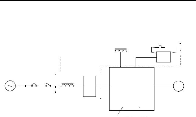
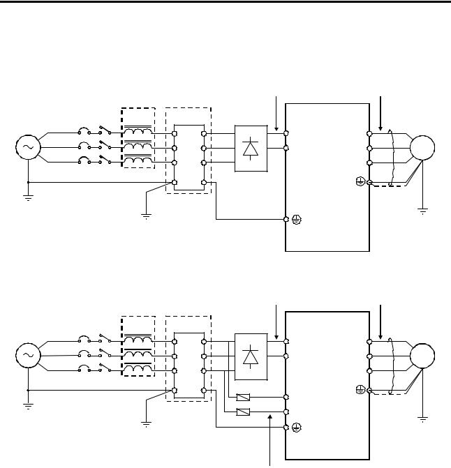
7-2 VAT2000’s main option
VAT2000 catalog numbers U2KxxxKxD, are for DC supply, allowing configurations in common bus.
(1) U2KX00K4D – U2KX37K0D, U2KN00K4D – U2KN07K5D
|
|
|
|
DC Power Supply (Note 1) |
|
Output Voltage (No te 2) |
|
AC L |
Noise Filter |
VAT20 00 |
|
|
|
M CCB M C |
(m ain optio n "D") |
|
|
|||
|
|
|
|
|
||
|
|
|
|
|
|
|
|
|
1 |
4 |
L + |
U |
|
|
|
2 |
5 |
L - |
V |
M |
|
|
3 |
6 |
|
W |
|
|
|
E |
E |
|
|
|
(2) U2KX45K0D, U2KN11K0D – U2KN37K0D
|
|
|
|
DC Power Supply (Note 1) |
|
Output Voltage (No te 2) |
|
AC L |
Noise Filter |
VAT2000 |
|
|
|
M CCB M C |
(m ain optio n "D") |
|
|
|||
|
|
|
|
|
||
|
|
1 |
4 |
L+ |
U |
|
|
|
2 |
5 |
L - |
V |
M |
|
|
3 |
6 |
|
W |
|
|
|
E |
E |
l1 |
|
|
|
|
|
|
|
|
|
|
|
|
|
l3 |
|
|
|
|
|
|
Fuse |
|
|
AC Control Power supply for FA N and / or MC of VAT2000 (Note 3)
(Note 1) DC Power Supply Voltage “X” type 520V-720V DC
“N” type 270V-360V DC
(Note 2) Output Voltage
“X” type Max. 480V AC “N” type Max. 230V AC
An output voltage exceeding the DC supply voltage / 1.35, can not be attained.
(Note 3) AC Control power supply for FAN and/or MC of VAT2000
“X” type 380V-460V ± 10% 50/60Hz ± 5%, 480V + 5% 50/60Hz ± 5%, “N” type 200V-230V ± 10% 50/60Hz ± 5%
7-4

7. Options
7-3 Built in PCB option
This is a built-in type option mounted on the VAT2000 control PCB.
As shown in table 7-1, there are three type of option PCBs, option I, option II and option III. The VAT2000 allows mounting up to three cards, but only one of each type.
These PCB options can be easily mounted after purchasing the VAT2000 by the end user.
* The PCB option cover is required when the PCB option is mounted.
Refer to each instruction manual for details on the PCB options.
7-3-1 Option classes
(1)Option I
This is a PCB option for speed detection during IM vector control with speed sensor and PM drive control. The mounting position is fixed.
*The PM drive control is applicable for the standard PM motor.
(2)Option II
This is the PCB option for an analog interface, etc. The mounting position is fixed.
(3)Option III
This is the PCB option for the relay interface, etc.
Built-in PCB option mounting drawing
7-5
7. Options
7-4 Dynamic braking (DBR).
The VAT2000 includes a dynamic braking feature in drives up to U2KN07K5S and U2KX07K5S . For larger drives the dynamic braking is achieved by using external modules
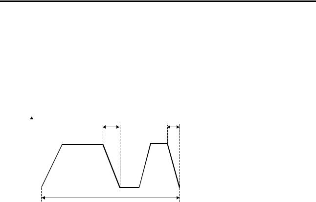
7-4-1 Units U2KN07K5S and smaller, and U2KX07K5S and smaller
These drives include a dynamic braking feature and a DB resistor as standard. The DBR device, allows operation cycle of 10% ED as shown in Fig. 7-2.
When using the dynamic braking option, set parameter B18-1, and C31-1, accordingly.
t1 |
t2 |
Speed
T ³10min
t1 + t2+ ... £ 1min.
T
Fig. 7-2
(1)Unit built-in DBR
The wiring of resistor built into the unit is shown in Fig. 7-3, and ratings are shown in table 7-3 Because of space restrictions, these resistors do not allow 100% of braking torque in some cases.
Table 7-3
Device |
Resistance |
Resistance |
Braking |
Max. |
|
Device |
Resistance |
Resistance |
Braking |
Max. |
type |
capacity |
value |
torque |
t1 |
|
type |
capacity |
value |
torque |
t1 |
U2KN |
(W) |
(Ω) |
(%) (1) |
(SEC) |
|
U2KX |
(W) |
(Ω) |
(%) |
(SEC) |
00K4S |
120 |
220 |
180 |
30 |
|
|
|
|
|
|
|
00K4S |
120 |
430 |
300 |
10 |
|||||
00K7S |
120 |
220 |
100 |
30 |
|
00K7S |
120 |
430 |
200 |
10 |
01K5S |
120 |
220 |
50 |
30 |
|
01K5S |
120 |
430 |
100 |
10 |
02K2S |
120 |
180 |
40 |
20 |
|
02K2S |
120 |
430 |
65 |
10 |
04K0S |
120 |
110 |
40 |
10 |
|
04K0S |
120 |
430 |
40 |
10 |
05K5S |
120 |
91 |
30 |
10 |
|
05K5S |
120 |
430 |
25 |
10 |
07K5S |
120 |
91 |
25 |
10 |
|
07K5S |
120 |
430 |
20 |
10 |
(Note 1) The braking torque is given for constant torque ratings. When using variable torque ratings, the braking torque is the value given for one frame smaller drive.
7-6