

General electric VAT2000
.pdf5. Control Input / Output
5-5 Sequence input logic
O peration Input |
Sequence signal |
|
F W D |
|
|
|
I |
Logic |
|
O peration by Keypad |
converter |
||
|
R E V |
||
|
|
||
Term inal block |
I |
|
|
|
|
||
RUN |
F RUN |
|
|
R RU N |
R RU N |
|
|
|
F.JO G |
Basic operation |
|
|
O F F |
||
|
R .JO G |
||
|
|
||
PSI1-9 |
HO LD |
|
|
BRA KE |
C O P |
||
|
|||
|
|
||
|
CSE L |
|
|
PSI |
IPAS S |
|
|
PIDEN |
|
||
|
|
||
|
CPASS |
|
|
|
VFS |
|
|
|
IFS |
|
|
|
AUX |
|
|
|
PRO G |
|
|
|
CFS |
|
|
|
CO P |
|
|
|
S0-S3 |
|
|
|
SE |
|
|
|
FUP |
|
|
O N |
FDW |
|
|
O FF |
BUP |
Auxiliary operation |
|
|
BDW |
|
|
|
IV LM |
|
|
|
AUX DV |
|
|
|
PICK |
|
|
|
EXC |
|
|
|
ACR |
|
|
|
PCTL |
|
|
|
LIM 1,2 |
|
|
|
M CH |
|
|
|
RF0 |
|
|
|
DRO O P |
|
|
|
DEDB |
|
|
|
TRQ B 1,2 |
|
|
|
F.RUN |
|
Basic operation |
|
|||||
|
|
||||||||
|
R .RU N |
|
|
|
|
|
|
|
|
|
|
|
|
|
|
|
|
|
|
|
F.JO G |
|
|
|
|
|
|
|
|
|
|
|
|
|
|
|
|
|
|
|
|
|
|
|
|
|
|
|
|
|
R .JO G |
|
|
|
|
|
|
|
|
|
|
|
|
|
|
|
|
|
|
tio n |
HO LD |
|
Auxiliary |
|
operation |
|
|||
|
|||||||||
|
|
|
|
|
|
|
|
||
BRA KE |
|
|
|
|
|
|
|
|
|
|
|
|
|
|
|
|
|
||
p |
|
|
Keypad |
|
|
|
|||
|
|
|
|
|
|||||
l O |
Sam e as |
|
|
|
|
||||
|
|
||||||||
|
|
|
|
|
|
|
|
||
eriaS |
term inal block |
|
|
R S T |
|||||
|
|
|
|
|
|
|
|
|
|
|
|
|
|
|
|
|
|
||
|
|
|
|
|
|
|
|
|
|
|
|
|
|
M O D |
|
|
|
||
|
|
|
|
|
|
||||
L C L
R E M
(Set w ith C00-5)
J 1
L C L
O F F
R E M
 C O P
C O P

 J 2
J 2
(Set w ith C00-6)
RES ET
EM S
RES ET
EM S
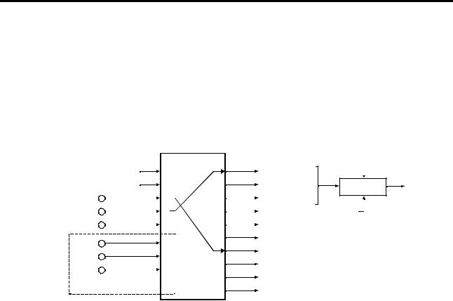
Fig. 5-2 Sequence input logic
Internal comm .
RUN
JO G
REV
HO LD
BRA KE
CSE L
IPAS S
PIDEN
CPASS
VFS
IFS
AUX
PRO G
CFS
CO P
S0
S1
S2
S3
SE
FUP
FDW
BUP
BDW
IV LM
AUX DV
PICK
EXC
ACR
PCTL
LIM 1
LIM 2
M CH
RF0
DRO O P
DEDB
TRQ B 1
TRQ B 2
RES ET
EM S
5-8

5. Control Input / Output
5-6 Changing of terminal functions
The programmable input terminals (PSI1 to PSI9) can be arbitrarily assigned to control internal commands. On the other hand the state of some internal functions can be connected to the programmable output terminals (RA-RC and PSO1 to PSO5) to lead out the ON/OFF signals.
5-6-1 Sequence input terminal assignment and monitoring
The functions that can be assigned to the terminal block are shown in Fig. 5-3. Each internal function can be fixed to ON (set value to 16) or OFF (set value to 0). If the function is set for example at “1”, then input PSI1 can switch that function ON/OFF. Fig 5-3 shows the default assignment, where R.RUN has been assigned to PSI1 input (C03-0=1).
Fig. 5-4 shows monitoring display allowed by parameter D04-0, 1, or 2. Thus the ON state of each internal signal can be known trough the operation panel display.
|
Term inal block |
||
puts |
|
O FF |
|
|
PSI1 |
||
l in |
|
PSI2 |
|
ita |
|
PSI3 |
|
f d ig |
|
||
|
PSI4 |
||
t o |
|
PSI5 |
|
ssigAne m en |
V2K2U3 RY O pOtio n |
||
PSI9 |
|||
|
|
PSI6 |
|
|
|
PSI7 |
|
|
|
PSI8 |
|
EM S 

F.R U N
O N
PSI
0
1
2
3
11
12
13
14
15
16
Internal comm and
C 03-0=1  R .R U N C 03-1=2
 F.JO G
C 03-2=3
 R .JO G
C 03-3
 HO LD
HO LD
C 03-4
 BRA KE
C 03-5
 CO P C 03-6
 CSE L
CSE L
C 03-7
 IPAS S
C 03-8
PIDEN
C04-0  CPASS C 04-1=16
 VFS C 04-2
 IFS
IFS
C04-3  AUX C04-4
 PRO G
PRO G
C04-5
 CSF
CSF
C04-6
 S0
S0
C04-7
 S1
S1
C04-8
 S2
S2
C04-9
 S3
S3
C05-0
 SE
SE
C05-1
 FUP C05-2
 FDW
FDW
C05-3  BUP C05-4
 BDW
BDW
C05-5
 IV LM C05-6
 AUX DV
C05-7  PICK C05-8
 EXC
EXC
C05-9
 ACR C06-0
 PCTL
PCTL
C06-1  LIM 1 C06-2
 LIM 2 C06-3
 M CH
M CH
C06-4  RF0 C06-5
 DRO O P
C06-6
 DEDB C06-7
 TRQ B 1
C06-8
TRQ B 2
CFS
PRO G
AUX
IFS
VFS
CPASS
IPAS S
CSE L
 EM S
EM S
RES ET RUN
REV JO G
EXC BRA KE
CO P D04-0 Display
LIM 2
LIM 1
PCTL
ACR
PICK
AUX DV
IV LM
BDW
 S0
S0
S1
S2
S3
SE
FUP
FDW
BUP |
D04-1 Display |
|
M CH |
RF0
DRO O P DEDB
TRQ B 1
TRQ B 2 D04-2 Display
PIDEN
Fig. 5-3 Assignment of sequence input |
Fig. 5-4 Sequence input monitor |
5-9

5. Control Input / Output
5-6-2 Sequence output terminal assignment and monitoring
The ON/OFF of the internal signals can be output to the RA-RC and PSO1 to 3-PSOE terminals as shown in Fig. 5-5 with the parameter Nos. C13-2 to 5 and C33. The ON/OFF of each signal can be monitored as shown in Fig. 5-6. This monitoring is executed with D04-3, 4.
Internal
Signal
|
|
|
PSO |
|
|
|
|
|
|
|
|
|
||||
R U N |
0 |
|
|
|
|
|
|
|
|
|
|
|
|
|
|
|
FLT |
1 |
(O u tp ut |
|
|
|
|
|
|
|
|
|
|||||
|
|
|
|
|
|
|
|
|
||||||||
fixe d ) |
|
|
|
|
|
|
|
|
|
|||||||
|
|
|
|
|
|
|
|
|
|
|
||||||
M C |
2 |
|
|
|
|
|
|
|
|
|
|
|
|
|
|
|
R D Y1 |
3 |
|
|
|
|
|
|
|
|
|
|
|
|
|
|
|
R D Y2 |
4 |
|
|
|
|
|
|
|
|
|
|
|
|
|
|
|
LC L |
5 |
C 1 3 -2 = 0 |
|
|
|
|
|
|
|
|
|
|||||
|
|
|
|
|
|
|
|
|
||||||||
R EV |
6 |
|
|
|
|
|
|
|
|
|
||||||
|
|
|
|
|
|
|
|
|
|
|
|
|
|
|
||
ID E T |
7 |
C 1 3 -3 = 3 |
|
|
|
|
|
|
|
|
|
|||||
ATN |
8 |
|
|
|
|
|
|
|
|
|
||||||
C 1 3 -4 = 7 |
|
|
|
|
|
|
|
|
|
|||||||
SPD 1 |
9 |
C 1 3 -5 = 8 |
|
|
|
|
|
|
|
|
|
|||||
SPD 2 |
10 |
|
|
|
|
|
|
|
|
|
|
|
|
|
|
|
C O P |
11 |
|
|
|
|
|
|
|
|
|
|
|
|
|
|
|
EC 0 |
12 |
|
|
|
|
|
|
|
|
|
|
|
|
|
|
|
EC 1 |
13 |
|
|
|
|
|
|
|
|
|
|
|
|
|
|
|
EC 2 |
14 |
|
|
|
|
|
|
|
|
|
|
|
|
|
|
|
EC 3 |
15 |
|
|
|
|
|
|
|
|
|
|
|
|
|
|
|
AC C |
16 |
|
|
|
|
|
|
|
|
|
|
|
|
|
|
|
D C C |
17 |
|
|
|
|
|
|
|
|
|
|
|
|
|
|
|
AU X D V |
18 |
|
|
|
|
|
|
|
|
|
|
|
|
|
|
|
ALM |
19 |
|
|
|
|
|
|
|
|
|
|
|
|
|
|
|
FAN |
20 |
|
|
|
|
|
|
|
|
|
|
|
|
|
|
|
ASW |
21 |
|
|
|
|
|
|
|
|
|
|
|
|
|
|
|
|
|
|
|
|
|
|
|
|
|
|
|
|
|
|
||
|
|
|
|
|
|
|
|
|
|
|
|
|
|
|
||
ZS P |
22 |
|
|
|
|
|
|
|
|
|
|
|
|
|
|
|
|
|
|
|
|
|
|
|
|
|
|
|
|
|
|
||
LLM T |
23 |
|
|
|
|
|
|
|
|
|
|
|
|
|
|
|
U LM T |
24 |
|
|
|
|
|
|
|
|
|
|
|
|
|
|
|
|
|
|
|
|
|
|
|
|
|
|
|
|
|
|
||
|
|
|
|
|
|
|
|
|
|
|
|
|
|
|
|
|
|
|
|
|
|
|
|
|
|
|
|
|
|
|
|
|
|
Term inal board
FA
FB
FC
R A
R C
PSO 1-3
PSO E
|
|
|
|
|
|
|
|
|
|
|
|
|
|
n |
|
|
|
|
|
|
|
|
|
|
|
|
|
|
|
|
|
|
|
|
PSO 4 |
|
ptioOYO3RV2 |
|||||||
|
|
|
|
|
|
|
||||||||
|
|
|
|
|
PSO 5 |
|
U 2K |
|||||||
|
|
|
|
|
|
|||||||||
|
|
|
|
|
|
|||||||||
|
|
|
|
|
|
|||||||||
|
|
|
|
|
|
|||||||||
|
|
|
|
|
|
|||||||||
|
|
|
|
|
|
|||||||||
|
|
|
|
|
|
|||||||||
|
|
|
|
|
|
|||||||||
|
|
|
|
|
|
|||||||||
|
|
|
|
|
|
|
|
|
|
|
|
|
|
|
|
|
|
|
|
|
|
|
|
|
|
|
|
|
|
|
|
|
|
|
|
|
|
|
|
|
|
|
|
|
|
|
|
|
|
|
|
|
|
|
|
|
|
|
n |
|
|
|
|
|
|
|
|
|
|
|
|
|
|
|
|
|
|
|
|
|
|
|
|
|
|
|
|
|
|
|
|
|
|
|
|
|
|
|
|
|
|
|
|
|
|
|
|
|
|
|
|
|
|
|
|
|
|
|
|
|
|
|
|
|
|
|
|
|
|
|
|
|
|
|
|
|
|
|
|
PSO 5 |
|
ptioO3PIOKV2 |
|||||||
|
|
|
|
|
PSO 4 |
|
U 2 |
|||||||
|
|
|
|
|
|
|||||||||
|
|
|
|
|
|
|
|
|
|
|
|
|
|
|
|
|
|
|
|
|
|
|
|
|
|
|
|
|
|
|
|
|
|
|
|
|
|
|
|
|
|
|
|
|
|
|
|
|
|
|
|
|
|
|
|
|
|
|
|
|
|
|
|
|
|
|
|
|
|
|
|
|
|
|
|
|
|
|
|
|
|
|
|
|
|
|
|
|
|
|
|
|
|
|
|
|
|
|
|
|
|
|
|
|
|
|
|
|
|
|
|
|
|
|
|
|
|
|
|
|
|
|
|
|
|
|
|
|
|
|
|
|
|
|
|
|
|
|
|
|
|
|
|
|
|
|
|
|
|
|
|
|
|
|
|
|
|
|
|
|
|
|
|
|
|
|
|
|
|
|
|
|
|
|
|
|
|
|
|
|
|
|
|
|
|
|
|
|
|
|
|
|
|
|
EC 3
EC 2
EC 1
EC 0
C O P
SPD 2
SPD 1
ATN
|
|
|
|
|
|
|
|
|
|
|
|
|
|
R U N |
|
|
|
|
|
|
|
|
|
|
|
|
|
||
|
|
|
|
|
|
|
|
|
|
|
|
FLT |
||
|
|
|
|
|
|
|
|
|
|
|
||||
|
|
|
|
|
|
|
|
|
|
M C |
||||
|
|
|
|
|
|
|
|
|
|
|||||
|
|
|
|
|
|
|
|
R D Y1 |
||||||
|
|
|
|
|
|
|
|
|||||||
|
|
|
|
|
|
|
R D Y2L |
|||||||
|
|
|
|
|
|
|
||||||||
|
|
|
|
|
LC L |
|||||||||
|
|
|
|
|
||||||||||
|
|
|
R EV |
|||||||||||
|
|
|
||||||||||||
|
ID E T |
|
|
|
|
|
|
(D04-3 display) |
||||||
|
|
|
|
|
|
|
||||||||
|
|
|
|
|
|
|
|
|
|
|
|
|
|
U LM T |
|
|
|
|
|
|
|
|
|
|
|
|
|
|
|
|
|
|
|
|
|
|
|
|
|
|
|
|
|
AC C |
|
|
|
|
|
|
|
|
|
|
|
|
|
|
|
|
|
|
|
|
|
|
|
|
|
|
|
|
|
|
|
|
|
|
|
|
|
|
|
|
|
|
|
|
|
|
|
|
|
|
|
|
|
|
|
|
|
D C C |
||
|
|
|
|
|
|
|
|
|
|
|
|
|||
|
|
|
|
|
|
|
|
|
|
AU X D V |
||||
|
|
|
|
|
|
|
|
|
|
|||||
|
|
|
|
|
|
|
|
ALM |
||||||
|
|
|
|
|
|
|
|
|||||||
|
|
|
|
|
|
|
FAN |
|||||||
|
|
|
|
|
|
|
||||||||
|
|
|
|
|
ASW |
|||||||||
|
|
|
|
|
||||||||||
|
|
|
ZS P |
|||||||||||
|
|
|
||||||||||||
|
LLM T |
|
|
|
|
|
|
(D04-4 Display) |
||||||
|
|
|
|
|
|
|
||||||||
Fig. 5-5 Assignment of sequence output |
Fig. 5-6 Sequence output monitor |
5-10

5. Control Input / Output
5-7 Programmable analog input function (PAI)
5-7-1 Types of analog inputs
The VAT2000 includes as standard three analog inputs to terminals FSV, FSI and AUX. Each analog input can be connected to the internal setting signals shown in Table 5-5 by using the programmable input function.
By connecting an analog interface option (type: U2KV23AD0), the programmable input terminals can be expanded to up to six channels.
Table 5-5 Types of internal setting signals assigned to analog input
|
|
Setting range (Note 1) |
|
|||
|
|
|
|
|
|
|
Signal name |
FSV |
FSI |
AUX |
Function |
||
|
|
|
||||
0-10V |
4-20mA |
0 - ±10V |
||||
|
|
|
||||
|
|
0-5V |
0-20mA |
0 - ±5V |
|
|
|
|
1-5V |
|
|
|
|
|
|
|
1-5V |
|
||
|
|
|
|
|
||
Speed setting 1 |
0~100% |
|
This is the speed setting. |
|||
Speed setting 2 |
|
|
−100~100% |
The (+) polarity is forward run, and the (-) polarity is the |
||
Speed setting 3 |
|
|
|
reverse run settings. |
||
|
|
|
When the speed setting by analog signal is enabled, |
|||
|
|
|
|
|
||
|
|
|
|
0~100% |
||
|
|
|
|
then setting 1,2,3 may be selected with the sequence |
||
|
|
|
|
|
||
|
|
|
|
|
input functions (VFS, IFS,AUX). |
|
Ratio interlock |
0~100% |
−100~100% |
This allows bias setting (C) to ratio interlock function |
|||
bias setting |
|
|
|
using an analog input. |
||
|
|
0~100% |
||||
|
|
|
|
|
||
Traverse |
|
0~100% |
0~10V |
This allows center frequency setting for traverse |
||
center |
|
|
|
0~5V |
operation, using an analog input. The positive polarity is |
|
frequency |
|
|
|
0~100% |
the forward run, and the negative polarity the reverse |
|
setting |
|
|
|
(Note 2) |
run. |
|
|
|
|
|
0~100% |
|
|
PID feedback |
0~100% |
0~10V |
This is used for feedback signal to the PID function, |
|||
|
|
|
|
0~5V |
using external sensor. |
|
|
|
|
|
0~100% |
Do not use the PID for speed control |
|
|
|
|
|
(Note 2) |
Do not use the programmable analog output (FM, AM) |
|
|
|
|
|
0~100% |
as PID’s feedback signal. |
|
Torque setting |
0~300% |
|
This is the analog setting for torque control. |
|||
|
|
|
|
−300~300% |
The (+) polarity is the forward direction torque, and the |
|
|
|
|
|
|
(–) polarity is the reverse direction torque. The torque |
|
|
|
|
|
|
setting can be limited by using the torque limiter |
|
|
|
|
|
0~100% |
||
|
|
|
|
function (A11-2, 3). |
||
|
|
|
|
|
||
Drive torque |
0~100% |
0~10V |
The drive torque limit (A10-3 or A11-2) may be reduced |
|||
limit reduction |
|
|
0~5V |
in percentage using an analog input. For example using |
||
setting |
|
|
|
0~100% |
a signal of 0V to +10V the limit torque is reduced from 0 |
|
|
|
|
|
(Note 2) |
to 100% |
|
|
|
|
|
0~100% |
This function is enabled when LIM1, is ON. |
|
Regenerative |
0~100% |
0~10V |
The regenerative torque limit (A10-4 or A11-3) may be |
|||
torque limit |
|
|
0~5V |
reduced in percentage using an analog input. |
||
reduction |
|
|
|
0~100% |
|
|
setting |
|
|
|
(Note 2) |
This function is enabled when LIM2 is ON. |
|
|
|
|
|
0~100% |
||
|
|
|
|
|
||
Torque bias 1 |
0~300% |
−300~300% |
A torque bias signal during either speed or torque |
|||
setting |
|
|
|
0~300% |
control is allowed using an analog input. |
|
|
|
|
|
0~300% |
This is enabled when the torque bias function TRQB1, |
|
|
|
|
|
|
is ON.. |
|
(Note 1) |
FSV, FSI, AUX inputs and modes are selected with C12-0 to 2. |
|||||
(Note 2) |
AUX: The setting is limited to 0% during the −10 to 0V and −5 to 0V input. |
|||||
5-11
5. Control Input / Output
5-7-2 Setting the analog input
The analog inputs can be randomly assigned to the internal setting signals given in Table 5-5 by setting parameters C07-0 to 9 as shown in Fig. 5-7.
For example if C07-0 (speed setting 1) is set to “0” this function is disabled; if it is set to “1” the speed setting function is fixed at 100%, but if C07-0 is set to “3”, then the speed setting 1 function can be controlled by terminal board input FSI. More details are given in section 6 (C07 parameter list).
An analog interface option type: U2KV23AD0 is necessary to use the additional analog inputs PAI1 to 3.
Term inal block |
|
|
Internal setting signal |
|
Panel setting |
||
|
|
PAI |
C07 |
-0=3 |
|
|
A, B |
|
|
|
|
|
|||
0% |
0 |
|
Speed setting 1 |
|
|
||
|
C07 |
-1 |
|
|
|||
(Note) 100% |
1 |
|
Speed setting 2 |
X |
Y |
||
|
C07 |
-2 |
|
Y=AX+B+C |
|||
FS V |
2 |
|
Speed setting 3 |
|
S p e ed |
||
|
|
|
|
s ettin g |
|||
FS I |
|
|
C07 |
-3 |
|
|
C |
3 |
|
Ratio Interlock bias setting |
|||||
|
C07 |
-4 |
|||||
AUX |
4 |
|
Traverse center frequency setting |
||||
|
C07 |
-5 |
|||||
|
|
|
PID feedback setting |
|
|||
PAI1 |
5 |
|
|
|
|
||
|
C07 |
-6=2 |
Torque setting |
|
|
||
PAI2 |
6 |
|
|
|
|||
|
C07 |
-7 |
D rive torque limiter reduction setting |
||||
|
|
|
|||||
PAI3 |
7 |
|
|
|
|||
|
C07 |
-8 |
Regenerative torque lim iter reduction setting |
||||
|
|
|
|||||
|
|
|
|
|
|||
U2KV23AD 0 O ption |
|
|
C07-9 |
Torque bias 1 setting |
|
||
|
|
|
|
|
|
||
.
(Note) The torque setting is 300% when C07-6 is 1.
Fig. 5-7 Analog input assignment
The sequential ratio operation can be carried out in respect to speed settings 1 to 3. (Refer to 6-5.)
5-12

5. Control Input / Output
5-8 Programmable analog output function (PAO)
5-8-1 Types of analog outputs
As a standard, there are two programmable analog outputs (10 bits) in the VAT2000, with terminal board numbers FM-COM, and AM-COM. Two more analog outputs are available by the optional PCB U2KV23TR0 (Trace Back option).
Each output can be programmed with the internal functions shown in Fig. 5-8. As default, FM is assigned as “output frequency” and AM is assigned as “Motor output current”.
Default settings
Terminal symbol |
Setting |
|
|
FM |
Output frequency |
|
|
AM |
Output current (Motor) |
5-8-2 Setting the analog output
The following internal data or functions can be output to FM, AM terminals by parameters C13-0 and C13- 1 as shown in Fig. 5-8.
The extended analog outputs AO1 and AO2, can be addressed with the internal data by parameters C39- 0 and C39-1.
If needed, the gain of analog outputs can be adjusted by parameters C14-0, C14-1.
Internal Data |
|
|
|
Term inal block |
|
|
|
PAO |
C 13-0=0 |
|
|
O utput frequency |
0 |
|
|
FM |
|
|
|
|
|||
Setting frequency (Setting speed) |
1 |
|
|
C 13-1=3 |
|
Cushion output |
2 |
|
|
AM |
|
|
|
|
|||
O utput current (M otor) |
3 |
|
|
|
|
|
|
|
|
||
O utput current (D rive) |
4 |
|
|
(C39-0) |
|
O utput voltage |
5 |
|
|
AO 1 |
|
O utput P ower (Drive) |
6 |
|
|
(C39-1) |
|
D C voltage |
7 |
|
|
AO 2 |
|
O LT Monitor |
8 |
|
|
|
|
Heat sink tem perature |
9 |
|
|
U2KV23TR O O ption |
|
M otor S peed |
10 |
|
|
|
|
Fig. 5-8 Analog output assignment
5-13

5. Control Input / Output
5-9 Selecting the setting data
5-9-1 Speed setting
(1)Speed setting selection
The speed setting in VAT2000 is possible from either analog input signals, or from host computer or from the operation panel. There are a total of nine different setting, all selectable.
Setting |
Setting data |
Explanation |
input point |
|
|
|
|
|
Analog |
Analog speed setting 1 |
The speed setting is possible from either of three analog |
|
Analog speed setting 2 |
inputs provided as standard in the VAT2000. |
|
Analog speed setting 3 |
|
Serial or |
Serial speed setting |
The speed setting is allowed from a host computer, through |
parallel |
|
the programmer port or using the serial interface option |
|
|
U2KV23SL0, or optional Profibus DP interface. |
|
Parallel speed setting |
The speed setting is allowed from a host PLC with parallel |
|
|
transmission. A PC interface option type U2KV23PI0 is |
|
|
required. |
Operation |
Speed setting |
The speed setting is allowed by parameter (A00-0 or 2). |
panel |
Panel jogging setting |
The speed setting is allowed by parameter (A00-1, 3). |
|
||
|
Traverse operation |
The speed setting is allowed by parameters (B44-0 to 6), when |
|
|
the “Traverse” function is enabled. |
|
Pattern Run operation |
The speed setting is allowed by parameters (B50-0 to B59-3), |
|
|
when the Pattern Run function is enabled |
|
|
|
(2)Speed setting selection sequence
The ratio of the speed setting (Ratio Interlock) and sequence control for signals is shown below. Refer to Section 6-5, B06 (Ratio interlock setting) for details.
An alog spee d setting 3 (C 07-2)
An alog spee d setting 2 (C 07-1)
An alog spee d setting 1 (C 07-0)
O peratio n Panel freque ncy (or s peed) setting (A00- 0, 2)
Serial com m unication spe ed setting
Traverse frequency (or s peed) setting (B44- 0 to 6)
Progr am frequency (or s peed) setting (B11 -0 to 7)
Panel Jog setting (A00- 1, 3)
Patern R un frequency (or s peed) setting (B50- 0 to B59 -3)
|
|
R atio In te rlock |
|
|
|
|
|
|
|
|
|
XXX |
Fu n ction s tha t can b e c o ntrolled O N / O FF |
|
|
|||||||||||
|
|
|
|
|
|
|
|
|
|
|
from te rm inal b oard |
|
|
|
|
|
||||||||||
|
|
|
|
|
|
|
|
|
|
|
|
|
|
|
|
|
|
|
|
|
|
|
|
|
||
|
|
AX+ B+ C |
|
|
|
|
|
|
|
|
|
|
|
|
|
|
|
|
|
|
|
|
|
|||
|
|
|
|
|
|
|
|
|
|
|
|
|
|
|
|
|
|
|
|
|
|
|
|
|||
|
|
R atio In te rlock |
|
|
|
|
|
|
|
|
|
|
|
|
|
|
|
|
|
|
|
|
||||
|
|
|
|
|
|
|
|
|
|
|
|
|
|
|
|
|
|
|
|
|
|
|
|
|||
|
|
AX+ B+ C |
|
|
|
|
|
|
|
|
|
|
|
|
|
|
|
|
|
|
|
Speed |
||||
|
|
|
|
|
|
|
|
|
|
|
|
|
|
|
|
|
|
|
|
|
|
|
C 02-0 |
|||
|
|
|
|
|
|
|
|
|
|
|
|
|
|
|
|
|
|
|
|
|
|
|
||||
|
|
R atio In te rlock |
|
|
|
|
|
on |
|
|
|
|
|
|
|
|
|
settting |
||||||||
|
|
|
|
on |
|
|
|
|
|
|
|
|
|
|
|
=1 |
|
|||||||||
|
|
AX+ B+ C |
|
on |
off |
|
|
|
|
|
|
|
|
|
|
|
|
|||||||||
|
|
|
off |
|
|
|
|
|
|
|
|
|
|
|
|
|
||||||||||
|
|
|
off |
|
AU X |
|
|
|
|
|
|
|
|
|
|
|
=2 |
|
||||||||
|
|
|
|
|
|
|
|
|
|
|
|
|
|
|
|
|
|
|
|
|
|
|
||||
|
|
|
|
|
|
|
|
VF S |
|
IFS |
|
|
|
|
|
|
|
|
|
|
|
|
|
|
||
|
|
|
|
|
|
|
|
|
|
|
|
|
|
|
|
|
|
|
|
|
|
|
|
=3 |
|
|
|
|
|
|
|
|
|
|
|
|
|
|
|
|
|
|
|
|
|
|
|
|
|
|
|
|
|
|
R atio In te rlock |
|
|
|
|
|
|
|
|
|
|
|
|
|
|
|
|
|
|
|||||||
|
|
|
|
|
|
|
|
|
|
|
|
|
|
|
|
|
|
|
=4 |
|
||||||
|
|
|
|
|
|
|
|
|
|
|
|
|
|
|
|
|
|
|
|
|
|
|
|
|
|
|
|
|
AX+ B+ C |
|
|
|
|
|
|
|
|
|
|
|
|
|
|
|
|
|
|
|
|
|
|
||
|
|
|
|
|
|
|
|
|
|
|
|
|
|
|
|
|
|
|
|
|
|
|
|
|
|
|
|
|
|
|
|
|
|
|
|
|
|
|
|
|
|
|
|
|
|
|
|
|
|
|
|
|
|
|
|
|
|
|
|
|
|
|
|
|
|
|
|
|
|
|
|
|
|
|
|
|
|
|
|
|
|
|
|
|
|
|
|
|
|
|
|
PR OG |
|
|
|
|
|
|
|
|
|
|
|
|
|
|
|
|
|
|
|
|
|
|
|
|
|
|
C FS |
|
|
JO G |
|
|
|
|
LC L |
|
|
|||||
|
|
|
|
|
|
|
|
|
|
|
|
|
on |
|
|
|
|
|
|
|
|
|||||
|
|
|
|
|
|
|
|
|
|
|
|
|
|
|
|
|
|
|
|
|
|
|||||
|
|
|
|
|
|
|
|
|
|
|
|
|
|
|
|
|
|
|
|
|
|
|
|
|
|
|
|
|
on =4 |
|
|
|
|
off |
|
off |
|
|
|
|
off |
|
on |
|
|
||||||||
|
|
off=4 |
|
|
|
|
|
|
|
|
|
|
|
off |
|
|
||||||||||
|
|
|
|
|
|
on |
|
|
|
|
|
|
on |
|
|
|
||||||||||
|
|
|
|
|
|
|
B40-0 |
|
|
|
|
|
|
|
|
|
|
|
B40-0 |
|
C 30-0 |
|
|
|||
|
|
|
|
|
|
|
|
|
|
|
|
|
|
|
|
|
|
|
|
|
|
|
|
|
||
|
|
|
|
|
|
|
|
|
|
|
|
|
|
|
|
|
|
|
|
off=3 |
|
off=1,2 |
|
|
||
|
|
|
|
|
|
|
|
|
|
|
|
|
|
|
|
|
|
|
|
on =3 |
|
|
|
|||
|
|
|
|
|
|
|
|
|
|
|
|
|
|
|
|
|
|
|
|
|
|
on =3,4,5 |
|
|
||
|
|
|
|
|
|
|
|
|
|
|
|
|
|
|
|
|
|
|
|
|
|
|
|
|
||
|
|
|
|
|
|
|
|
|
|
|
|
|
|
|
|
|
|
|
|
|
|
|
|
|
|
|
|
|
|
|
|
|
|
|
|
|
|
|
|
|
|
|
|
|
|
|
|
|
R FO |
|
|
|
|
|
|
|
|
|
|
|
|
|
|
|
|
|
|
|
|
|
|
|
|
|
off |
|
|
|
|
|
|
|
|
|
|
|
|
|
|
|
|
|
|
|
|
|
|
|
|
|
|
on |
|
|
|
|
|
|
|
|
|
|
|
|
|
|
|
|
|
|
|
|
|
|
|
0 |
|
|
|
|
|
|||
Fig. 5-9 Speed setting selection
5-14

5. Control Input / Output
5-9-2 Torque setting
(1)Torque setting selection
The torque setting in VAT2000 is possible from either analog signals, serial communications or from the operation panel. All these are selectable by the user.
Setting |
Setting data |
Explanation |
input point |
|
|
Analog |
Analog torque setting |
The torque setting is possible from the analog input. |
Serial |
Serial torque setting |
The torque setting is allowed from a host computer with |
|
|
serial transmission. |
|
|
A serial interface option type U2KV23SL0 is required. |
Panel |
Panel torque setting |
The torque setting is allowed by parameter (B13-2). |
|
|
|
(2)Torque setting selection sequence
The torque setting interlock sequence is shown below.
Analog Torque setting (C07-6)
Serial com munication Torque setting
O peration Panel Torque setting (B13-0)
XXXFunctions that can be controlled O N / OFF from term inal board
|
CFS |
|
|
Forward Run |
|
o ff |
LCL |
C02-2 |
|
|
|
o n |
o ff |
=1 |
|
Torque setting |
|
o n |
-1 |
||||
|
|
Reverse R un |
|||
|
|
=2 |
|
||
|
|
|
|
||
|
|
=3 |
|
|
|
|
|
=4 |
|
|
Fig. 5-10 Torque setting selection
5-15
5. Control Input / Output
5-9-3 Torque bias 1 setting
(1)Torque bias 1 setting selection
A torque bias setting is possible from either analog signals, serial communications or from the operation panel. All these are selectable by the user.
Setting |
Setting data |
Explanation |
input point |
|
|
Analog |
Analog torque bias 1 |
This torque bias setting is possible from an analog input. |
|
setting |
|
Serial |
Serial torque bias 1 |
This torque setting is allowed from a host computer with |
|
setting |
serial transmission. |
|
|
A serial interface option type U2KV23SL0 is required. |
Panel |
Panel torque bias 1 |
This torque bias setting is allowed by parameter (B13-0). |
|
setting |
|
(2)Torque bias 1 setting selection sequence
The relation of the torque bias 1 setting and changeover sequence is shown below.
XXXFunctions that can be controlled O N / OFF from terminal board
Analog Torque |
|
|
|
|
|
|
|
|
|
|
|
|
bias 1 setting (C07-9) |
|
|
|
|
|
|
|
|
|
|
|
|
o ff |
CFS |
|
|
|
|
|
|
|
|
|
||
|
|
|
|
|
|
|
|
|
|
|||
Serial com munication Torque |
o n |
o ff |
LCL |
C02-4 |
|
|
|
TRQ B 1 |
|
|||
bias 1 setting |
|
|
o n |
|
=1 |
o n |
|
|
|
|
||
|
|
|
|
|
|
|
|
o ff |
|
|
Torque bias 1 |
|
|
|
|
|
|
|
=2 |
|
|
setting |
|||
|
|
|
|
|
|
|
0 |
|||||
|
|
|
|
|
|
|
|
|
|
|
||
O peration panel |
|
|
|
|
|
=3 |
|
|
|
|
|
|
|
|
|
|
|
|
|
|
|
|
|
|
|
Torque bias 1 setting |
|
|
|
|
|
=4 |
|
|
|
|
|
|
(B13-2) |
|
|
|
|
|
|
|
|
|
|
||
Fig. 5-11 Torque bias 1 setting selection
5-9-4 Torque limiter function
(1)Torque limit setting selection
The torque limit can be set independently for both speed control (ASR mode) or torque control (ACR mode) independently for drive or regeneration status. If the VAT2000 is stopped by the emergency stop signal (EMS), then the regeneration limit is fixed by parameter A10-5.
The parameters used in the torque limiter function are shown below..
A10-3 : ASR drive torque limit setting
A10-4 : ASR regenerative torque limit setting
A10-5 : Emergency stop regenerative torque limit setting
A11-2 : ACR drive torque limit setting
A11-3 : ACR regenerative torque limit setting
The value of above limits can be reduced by external settings. The final limit value results multiplying the above selected limit with the reduction ratio.
5-16

5. Control Input / Output
(1-1) External reduction setting
The torque limit can be reduced using the signal provided from an analog input or from the serial transmission . Either analog or serial signals can be selected by setting a parameter or from the drive’s terminal board.
Setting |
Setting data |
Explanation |
input point |
|
|
|
Analog drive torque limit |
The drive torque limit (A10-3 or A11-2) may be reduced in |
|
reduction setting |
percentage using an analog input. For example using a |
Analog |
|
signal of 0V to +10V the limit torque is reduced from 0 to |
|
|
100%. |
|
|
This function is enabled when LIM1, is ON. |
|
Analog regenerative |
The regenerative torque limit (A10-4, A10-5 or A11-3) may |
|
torque limit reduction |
be reduced in percentage using an analog input. For |
|
setting |
example using a signal of 0V to +10V the limit torque is |
|
|
reduced from 0 to 100%. |
|
|
This function is enabled when LIM2 is ON. |
|
Serial drive torque limit |
A serial interface option U2KV23SL0. |
Serial |
reduction setting |
The drive torque limit (A10-3, A11-2), may be reduced in a |
|
percentage using the data 0 to 100% provided from serial |
|
|
|
transmission. |
|
|
For example using a signal of 0 to 100% the limit torque is |
|
|
reduced from 0 to 100%. |
|
|
This function is enabled when LIM1 is ON. |
|
Serial regenerative |
A serial interface option U2KV23SL0 |
|
torque limit reduction |
The regenerative torque limit (A10-4, A10-5, A11-3), may |
|
setting |
be reduced in a percentage using the data 0 to 100% |
|
|
provided from serial transmission. |
|
|
For example using a signal of 0 to 100% the limit torque is |
|
|
reduced from 0 to 100%. |
|
|
This function is enabled when LIM2 is ON. |
(1-2) Internal reduction setting
The torque limit may be reduced as well by setting a value lower than 100% in the parameter “Double rating speed ratio”, B13-4. The reduction generated in the limiter function, in percentage, is shown below, and will depend of the base speed and real speed ratio. The resultant multiplier will reduce the limit values set in A10-3, A11-2, A10-4, A10-5 and A11-3.
R e du ctio n ratio (% )
100% |
KDB L (% ) x NB ASE (rpm ) |
|
|
|
N FB (rpm) |
|
KDB L |
 Speed (rpm )
NDBL NBA SE |
NM AX |
KDBL |
: B13-4 |
|
Double rating speed ratio (%) |
NFB |
: Speed detection (rpm) |
NBASE : Base speed (rpm) |
|
NDBL |
: NBASE x KDBL (rpm) |
5-17