


Control technology and radiation protection programme
to be recognizable and readable from a distance of 3 metres. Proper hazard communication is essential, as seen in the box below:
An example of improper communication is given by Ruggera and Schaurburt, 1982. "During a visit to a user facility a large banner was observed hanging from the ceiling. It was intended to warn the operators not to come within 1 metre of the RF sealer when it was on. This method of exposure control could have been effective, since the "on" and "off" controls of the RF sealer were located on pedestals that had enough connecting cable to allow them to be placed 3 feet from the machine. It was observed, however, that the operators were located approximately 1 foot in front of the unit where exposure fields were higher than the recommended maximum RF field strengths. During the radiation measurements, one of the operators remarked that the investigator should go behind the machine to measure the fields – the sign was hanging above the back of the machine and the operator had assumed that the high fields to be avoided were under the sign (that is, behind the sealer near the AC power lines)."
The evacuation of hazard areas prior to RF application must be strictly enforced. Because of rigid production schedules, some operators are tempted to violate the RF hazard area in front of the RF heater. For example, a procedure which requires the operator to first load the heater, step back 2 metres to get outside the RF hazard area prior to activating the RF energy, and then walk back to unload the heater will be considered an impediment to rapid production. The additional time required and increased operator fatigue will discourage operators from following such procedures, particularly for workers who are paid on a piece-work production basis.
Physical barriers can also be used to ensure that operators and other workers remain outside of the RF hazard areas. To be effective, the barriers must not be easily movable or be electrically conducting. Reactive fields emanating from the RF heater can induce currents in nearby conducting barriers and other objects. Workers' contact with these metal objects can result in shocks or burns. Natural barriers such as walls, tables and fixtures to hold the workload are preferable.
8.3. Design and installation considerations
8.3.1. Shielding
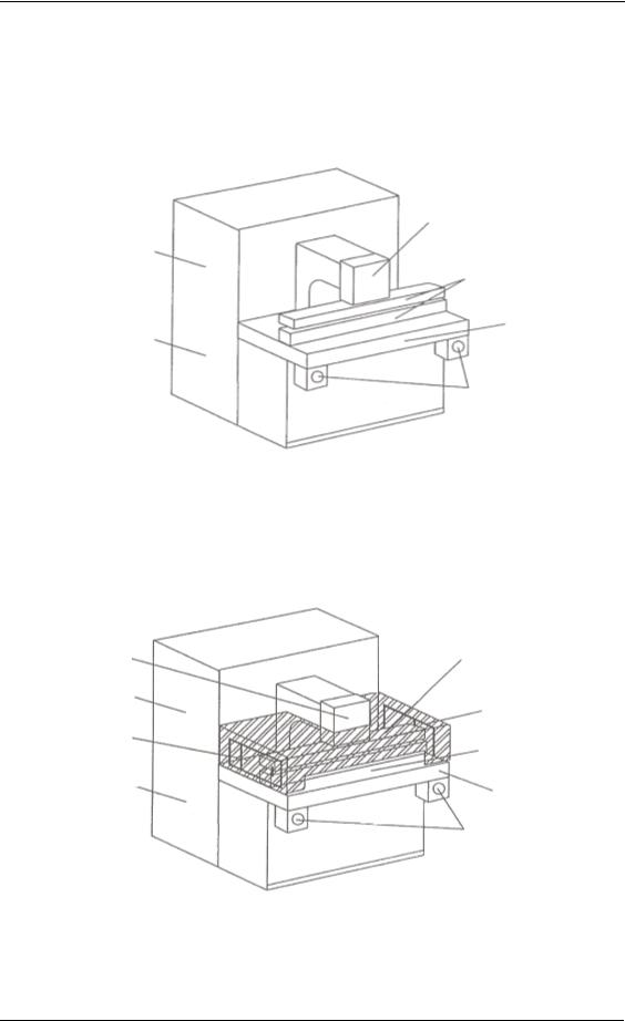
Although work practices and administrative controls can and should be used to reduce worker exposure, the use of shielding is emphasized in this document because it is more effective, dependable and efficient. Because many applications of dielectric heaters are unique, they will require variations in the shielding design. Murray et al. (1992) give additional details concerning effective shielding of an RF heater requiring an innovative design. Additional background information is given in the appendices. The ideal shield will be a complete conducting closure containing the RF applicator (see figure 4).
23
Safety in the use of RF heaters and sealers
Figure 4. Unshielded and shielded RF heater used in the study
Unshielded
|
Press yoke |
Oscillator |
Applicator (parallel plates) |
|
|
Power supply |
Base plate |
|
|
|
Control switches |
Shielded
Press yoke |
Shield |
Oscillator |
Sliding. interlocking door |
|
|
Sliding |
Slot in shield |
interlocking door |
|
Power supply |
Base plate |
|
|
|
Control switches |
24

Control technology and radiation protection programme
Four basic principles for the successful application of shielding can be summarized as follows:
(1)The shield (including the joints) should have very high conductivity (i.e. low resistance and reactance) for all interior currents that will flow in the walls.
(2)Openings in the cabinet should be as small as possible, consistent with effective machine operation, and the number of openings kept to a minimum. The orientation of the openings to current paths should be selected to minimize worker exposure.
(3)Currents in the shield walls should be minimized by having separate conductors inside the cabinet to carry high currents.
(4)Improperly installed shielding can increase RF energy leakage. Initial and periodic followup RF radiation surveys must be made.
When designing shielding, suggestions from the workers should be considered because of their experience in using the equipment. As long as their ideas do not decrease the effectiveness of the shield, they may be incorporated into the shield design.
Good shielding designs should interfere as little as possible with the normal operating procedures and production requirements.
The necessity of following the principles of shielding RF equipment is demonstrated throughout this document. Omitting "minor" details can result in an ineffective shield. For example, the use of fewer screws decreases conductivity and can allow RF energy to leak through joints.
An effective shield can be easily incorporated into the original design of the RF heater. Retrofitting shielding on older equipment is often necessary. However, modifying existing equipment is sometimes difficult and requires ingenuity to solve the mechanical and electrical problems. An effective retrofitting of shields is described by Murray et al. (1992).
Sometimes mechanical power is used to operate movable parts of the shield, such as a door. Mechanical power can be transmitted by linkages from auxiliary equipment, such as an electric motor, or a pneumatic or hydraulic cylinder. The type of power source used will depend on what is available and easiest to utilize.
Implementation of the four principles of shielding given above has been successful in many installations. The most critical step is the final one, since a shield's effectiveness can only be judged by measuring the operator's exposure according to the procedures in Chapter 7. If the exposure is above recommended levels, the points of leakage must be found and corrected. The importance of routine periodic RF surveys is often overlooked. Mechanical and electrical connections often deteriorate over time because of vibration, mechanical stress, heat, etc., resulting in reduced effectiveness of the shield. Also, because a current tends to crowd towards both ends of a slot across the current path, the use of a field strength probe to find leaks can be misleading. Leaks may appear to be near a screw, even if the screw has been tightened. In this case, the spot between screws should be inspected; there is probably poor electrical contact between shield parts. If the screws are spaced too far apart, more screws may have to be
25