

1.2.3.5 Space Division Multiple Access
The SDMA scheme also referred to as space diversity uses an array of antennas to provide control of space by providing virtual channels in angle domain [38]. This scheme exploits the directivity and beamshaping capability of an array of antennas to reduce co-channel interference. Thus, it is possible that by using this scheme simultaneous calls in a cell could be established at the same carrier frequency. This helps to increase the capacity of a cellular system.
The scheme is based on the fact that a signal arriving from a distant source reaches different antennas in an array at different times as a result of their spatial distribution, and this delay is utilized to differentiate one or more users in one area from those in another area. The scheme allows an effective transmission to take place between a base station and a mobile without disturbing the transmission to other mobiles. Thus, it has the potential such that the shape of a cell may be changed dynamically to reflect the user movement instead of currently used fixed size cells. This arrangement then is able to create an extra dimension by providing dynamic control in space [39, 40]. A number of chapters in this book deal with various aspects of antenna array processing.
1.2.4 Channel Reuse
The generic term channel is normally used to denote a frequency in FDMA system, a time slot in TDMA system, and a code in CDMA system or a combination of these in a mixed system. Two channels are different if they use different combinations of these at the same place. For example, two channels in a FDMA system use two different frequencies. Similarly, in TDMA system two separate time slots using the same frequency channel is considered two different channels. In that sense, for an allocated spectrum the number of channels in a system is limited. This limits the capacity of the system to sustain simultaneous calls and may only be increased by using each traffic channel to carry many calls simultaneously. Using the same channel again and again is one way of doing it. This is the concept of channel reuse.
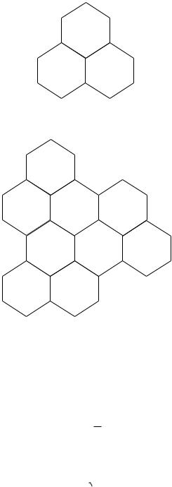
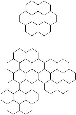
The concept of channel reuse can be understood from Fig. 1.2. Figure 1.2a shows a cluster of three cells. These cells use three separate sets of channels. This set is indicated by a letter. Thus, one cell uses set A, the other uses set B, and so on. In Fig. 1.2b this cluster of three cells is being repeated to indicate that three sets of channels are being reused in different cells. Figure 1.3 shows a similar arrangement with cluster size of seven cells. Now let us see how this helps to increase the system capacity.
Assume there are a total of F channels in a system to be used over a given geographic area. Also assume that there are N cells in a cluster that use all the available channels. In the absence of channel reuse this cluster covers the whole area and the capacity of the system to sustain simultaneous calls is F. Now if the cluster of N cells is repeated M times over the same area, then the system capacity increases to MF as each channel is used M times.
The number of cells in a cluster is referred to as the cluster size, the parameter 1/N is referred to as the frequency reuse factor, and a system using a cluster size of N sometimes is also referred to as a system using N frequency reuse plan. The cluster size is an important parameter. For a given cell size, as the cluster size is decreased, more clusters are required to cover the given area leading to more reuse of channels and hence the system capacity increases. Theoretically, the maximum capacity is attained when cluster size is one, that is, when all the available channels are reused in each cell. For hexagonal cell geometry, the cluster size can only have certain values. These are given by N = i2 + j2 + ij, where i and j are nonnegative integers.
The cells using the same set of channels are known as co-channel cells. For example, in Fig. 1.2, the cells using channels A are co-channel cells. The distance between co-channel cells is known as co-channel distance and the interference caused by the radiation from these cells is referred to as co-channel interference. For proper functioning of the system, this needs to be minimized by decreasing the power transmitted by mobiles and base stations in co-channel cells and increasing the co-channel distance. Because the transmitted power normally depends on the cell size, the minimization of co-channel interference requires a minimum co-channel distance; that is, the distance cannot be smaller than this minimum distance.
© 2002 by CRC Press LLC
A
C B
A |
|
|
C |
B |
A |
A |
C |
B |
C |
B |
|
FIGURE 1.2 (a) A cluster of three cells. (b) Channel reuse concept using a three-cell cluster.
In a cellular system of equal cell size, the co-channel interference is a function of a dimensionless parameter known as co-channel reuse ratio Q. This is a ratio of the co-channel distance D and the cell radius R, that is,
Q = D
R
For hexagonal geometry,
Q = 3N
It follows from these equations that an increase in Q increases the co-channel distance and thus minimizes the co-channel interference. On the other hand, a decrease in Q decreases the cluster size N and hence maximizes the system capacity. Thus, the selection of Q is a trade-off between the two parameters, namely, the system capacity and co-channel interferences. It should be noted that for proper functioning of the system, the signal to co-channel interference ratio should be above a certain minimum value [19].
© 2002 by CRC Press LLC
B G
C A F
D E
|
B |
G |
|
|
|
C |
A |
F |
|
B |
G |
|
D |
E |
C |
A |
F |
B |
G |
|
|
D |
E |
C |
A |
F |
|
|
|
D E
FIGURE 1.3 (a) A cluster of seven cells. (b) Channel reuse concept using a seven-cell cluster.
1.2.5 Cellular Configuration
A cellular system may be referred to as a macrocell, a microcell, or a picocell system depending on the size of cells. Some characteristics of these cellular structures are now described.
1.2.5.1 Macrocell System
A cellular system with its cell size of several kilometers is referred to as macrocell systems. Base stations of these systems transmit several watts of power from antennas mounted on high towers. Normally there is no line of sight (LOS) between the base station and mobiles and thus a typical received signal is a combination of various signals arriving from different directions. The received signal in these systems experience spreading of several microseconds because of the nature of propagation conditions.
1.2.5.2 Microcell Systems
As cells are split and their boundaries are redefined, their size becomes very small. At a radius less than about a kilometer, the system is referred to as a microcell system. In these systems a typical base station transmits less than 1 W of power from an antenna mounted at a few meters above the ground and normally an LOS exists between the base and a mobile. Cell radius in microcell systems is less than a kilometer giving rms delay spread on the order of few tens of nanoseconds compared with a few micoseconds for macrocell systems. This impacts on the maximum data rate a channel could sustain. For microcell systems maximum bit rate is about 1 Mbps compared with that of about 300 kbps for macocell systems [27].
Microcell systems are also useful in providing coverage along roads and highways. Because the antenna height is normally lower than the surrounding buildings the propagation is along the streets and an LOS
© 2002 by CRC Press LLC