

Правила Кодексы / МАРПОЛ / AIR_POLLUTION_AND_ENERGY_EFFICIENCY
.pdfMEPC 64/INF.22
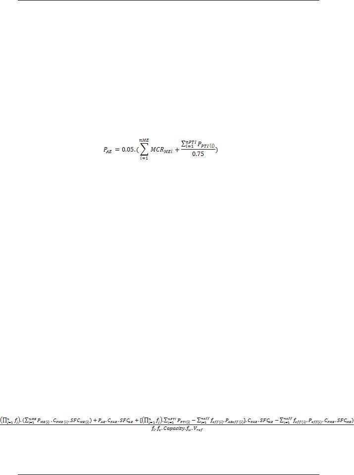
Annex, page 29
|
|
|
Mech. |
El. |
|
Rated |
load |
duty |
time |
use |
Necessary |
|
|
|
|
Efficien. |
el. |
||||||||
Id |
Group |
Description |
Power |
Motor |
factor |
factor |
factor |
factor |
power |
|||
"e" |
Power |
|||||||||||
|
|
|
"Pm" |
output |
"kl" |
"kd" |
"kt" |
"ku" |
"Pload" |
|||
|
|
|
|
"Pr" |
||||||||
|
|
|
|
|
|
|
|
|
|
|
||
13 |
B |
MAIN COOLING SEA WATER PUMP NO.3 |
28,0 |
30 |
0,925 |
30,3 |
0,9 |
0,66 |
1 |
0,59 |
18,0 |
|
|
|
|
|
|
|
|
|
|
|
|
|
|
14 |
B |
LT COOLING FW PUMP NO.1 |
28,0 |
30 |
0,925 |
30,3 |
0,9 |
0,66 |
1 |
0,59 |
18,0 |
|
|
|
|
|
|
|
|
|
|
|
|
|
|
15 |
B |
LT COOLING FW PUMP NO.2 |
28,0 |
30 |
0,925 |
30,3 |
0,9 |
0,66 |
1 |
0,59 |
18,0 |
|
|
|
|
|
|
|
|
|
|
|
|
|
|
16 |
B |
LT COOLING FW PUMP NO.3 |
28,0 |
30 |
0,925 |
30,3 |
0,9 |
0,66 |
1 |
0,59 |
18,0 |
|
|
|
|
|
|
|
|
|
|
|
|
|
|
17 |
B |
M/E COOLING WATER PUMP NO.1 |
13,0 |
15 |
0,9 |
14,4 |
1 |
0,5 |
1 |
0,50 |
7,2 |
|
|
|
|
|
|
|
|
|
|
|
|
|
|
18 |
B |
M/E COOLING WATER PUMP NO.2 |
13,0 |
15 |
0,9 |
14,4 |
1 |
0,5 |
1 |
0,50 |
7,2 |
|
|
|
|
|
|
|
|
|
|
|
|
|
|
19 |
C |
MAIN LUB. OIL PUMP NO.1 |
55,0 |
90 |
0,94 |
58,5 |
0,9 |
0,5 |
1 |
0,45 |
26,3 |
|
|
|
|
|
|
|
|
|
|
|
|
|
|
20 |
C |
MAIN LUB. OIL PUMP NO.2 |
55,0 |
90 |
0,94 |
58,5 |
0,9 |
0,5 |
1 |
0,45 |
26,3 |
|
|
|
|
|
|
|
|
|
|
|
|
|
|
21 |
C |
H.F.O. TRANSFER PUMP |
6,0 |
7,5 |
0,88 |
6,8 |
1 |
1 |
0,1 |
0,10 |
0,7 |
|
|
|
|
|
|
|
|
|
|
|
|
|
|
22 |
C |
D.O. TRANSFER PUMP |
6,0 |
7,5 |
0,88 |
6,8 |
1 |
1 |
0,1 |
0,10 |
0,7 |
|
|
|
|
|
|
|
|
|
|
|
|
|
|
23 |
C |
L.O. TRANSFER PUMP |
1,4 |
2,5 |
0,8 |
1,8 |
1 |
1 |
0,1 |
0,10 |
0,2 |
|
|
|
|
|
|
|
|
|
|
|
|
|
|
24 |
C |
TECHNICAL FRESH WATER PUMP NO.1 |
2,5 |
3,5 |
0,85 |
2,9 |
1 |
0,5 |
0,1 |
0,05 |
0,1 |
|
|
|
|
|
|
|
|
|
|
|
|
|
|
25 |
C |
TECHNICAL FRESH WATER PUMP NO.2 |
2,5 |
3,5 |
0,85 |
2,9 |
1 |
0,5 |
0,1 |
0,05 |
0,1 |
|
|
|
|
|
|
|
|
|
|
|
|
|
|
26 |
C |
E/R SUPPLY FAN NO.1 |
14,0 |
20 |
0,9 |
15,5 |
0,9 |
1 |
1 |
0,90 |
14,0 |
|
|
|
|
|
|
|
|
|
|
|
|
|
|
27 |
C |
E/R SUPPLY FAN NO.2 |
14,0 |
20 |
0,9 |
15,5 |
0,9 |
1 |
1 |
0,90 |
14,0 |
|
|
|
|
|
|
|
|
|
|
|
|
|
|
28 |
C |
E/R SUPPLY FAN NO.3 |
14,0 |
20 |
0,9 |
15,5 |
0,9 |
1 |
1 |
0,90 |
14,0 |
|
|
|
|
|
|
|
|
|
|
|
|
|
|
29 |
C |
E/R SUPPLY FAN NO.4 |
14,0 |
20 |
0,9 |
15,5 |
0,9 |
1 |
1 |
0,90 |
14,0 |
|
|
|
|
|
|
|
|
|
|
|
|
|
|
30 |
C |
PURIFIER ROOM EXH.VENTILATOR |
2,5 |
3 |
0,82 |
3,0 |
0,9 |
1 |
1 |
0,90 |
2,7 |
|
|
|
|
|
|
|
|
|
|
|
|
|
|
31 |
C |
PUMP HFO SUPPLY UNIT NO.1 |
2,1 |
3 |
0,8 |
2,6 |
0,9 |
0,5 |
1 |
0,45 |
1,2 |
|
|
|
|
|
|
|
|
|
|
|
|
|
|
32 |
C |
PUMP HFO SUPPLY UNIT NO.2 |
2,1 |
3 |
0,8 |
2,6 |
0,9 |
0,5 |
1 |
0,45 |
1,2 |
|
|
|
|
|
|
|
|
|
|
|
|
|
|
33 |
C |
CIRC. PUMP FOR HFO SUPPLY UNIT NO.1 |
2,8 |
3,5 |
0,84 |
3,3 |
0,9 |
0,5 |
1 |
0,45 |
1,5 |
|
|
|
|
|
|
|
|
|
|
|
|
|
|
34 |
C |
CIRC. PUMP FOR HFO SUPPLY UNIT NO.2 |
2,8 |
3,5 |
0,84 |
3,3 |
0,9 |
0,5 |
1 |
0,45 |
1,5 |
|
|
|
|
|
|
|
|
|
|
|
|
|
|
35 |
C |
H.F.O. SEPARATOR NO.1 |
N.A. |
N.A. |
N.A. |
6,5 |
0,9 |
0,5 |
0,9 |
0,41 |
2,6 |
|
|
|
|
|
|
|
|
|
|
|
|
|
|
36 |
C |
H.F.O. SEPARATOR NO.2 |
N.A. |
N.A. |
N.A. |
6,5 |
0,9 |
0,5 |
0,9 |
0,41 |
2,6 |
|
|
|
|
|
|
|
|
|
|
|
|
|
|
37 |
C |
MAIN AIR COMPRESSER NO.1 |
N.A. |
N.A. |
N.A. |
43,0 |
1 |
0,5 |
0,1 |
0,05 |
2,2 |
|
|
|
|
|
|
|
|
|
|
|
|
|
|
38 |
C |
MAIN AIR COMPRESSER NO.2 |
N.A. |
N.A. |
N.A. |
43,0 |
1 |
0,5 |
0,1 |
0,05 |
2,2 |
|
|
|
|
|
|
|
|
|
|
|
|
|
|
39 |
C |
SERVICE AIR COMPRESSER |
N.A. |
N.A. |
N.A. |
22,0 |
1 |
1 |
0,1 |
0,10 |
2,2 |
|
|
|
|
|
|
|
|
|
|
|
|
|
|
40 |
C |
VENT. AIR SUPPLY |
N.A. |
N.A. |
N.A. |
1,0 |
1 |
1 |
0,5 |
0,50 |
0,1 |
|
|
|
|
|
|
|
|
|
|
|
|
|
|
41 |
C |
BILGE WATER SEPARATOR |
N.A. |
N.A. |
N.A. |
1,5 |
1 |
1 |
0,1 |
0,10 |
0,2 |
|
|
|
|
|
|
|
|
|
|
|
|
|
|
42 |
C |
M/E L.O. SEPARATOR |
N.A. |
N.A. |
N.A. |
6,5 |
0,9 |
1 |
0,2 |
0,18 |
1,2 |
|
|
|
|
|
|
|
|
|
|
|
|
|
|
43 |
C |
G/E L.O. SEPARATOR |
N.A. |
N.A. |
N.A. |
6,5 |
0,9 |
1 |
0,2 |
0,18 |
1,2 |
|
|
|
|
|
|
|
|
|
|
|
|
|
|
44 |
D |
HYDROPHORE PUMP NO.1 |
2,8 |
4 |
0,84 |
3,3 |
1 |
0,5 |
0,1 |
0,05 |
0,2 |
|
|
|
|
|
|
|
|
|
|
|
|
|
|
45 |
D |
HYDROPHORE PUMP NO.2 |
2,8 |
4 |
0,84 |
3,3 |
1 |
0,5 |
0,1 |
0,05 |
0,2 |
|
|
|
|
|
|
|
|
|
|
|
|
|
|
46 |
D |
HOT WATER CIRCULATING PUMP NO.1 |
0,5 |
1,0 |
0,8 |
0,8 |
1 |
0,5 |
0,2 |
0,10 |
0,1 |
|
|
|
|
|
|
|
|
|
|
|
|
|
|
47 |
D |
HOT WATER CIRCULATING PUMP NO.2 |
0,5 |
1,0 |
0,8 |
0,8 |
1 |
0,5 |
0,2 |
0,10 |
0,1 |
|
|
|
|
|
|
|
|
|
|
|
|
|
|
48 |
E |
E/R WORKSHOP WELDING SPACE EXH. |
0,5 |
0,8 |
0,8 |
0,6 |
0,9 |
1 |
1 |
0,90 |
0,6 |
|
|
|
|
|
|
|
|
|
|
|
|
|
|
49 |
F |
ECR COOLER UNIT |
N.A. |
N.A. |
N.A. |
4,2 |
1 |
1 |
0,5 |
0,50 |
2,1 |
|
|
|
|
|
|
|
|
|
|
|
|
|
|
50 |
F |
FAN FOR AIR CONDITIONING PLANT |
N.A. |
N.A. |
N.A. |
8,0 |
0,9 |
1 |
0,5 |
0,45 |
3,6 |
|
|
|
|
|
|
|
|
|
|
|
|
|
|
51 |
F |
COMP. AIR CONDITIONING PLANT NO.1 |
N.A. |
N.A. |
N.A. |
10,0 |
0,9 |
1 |
0,5 |
0,45 |
4,5 |
|
|
|
|
|
|
|
|
|
|
|
|
|
|
52 |
F |
COMP. AIR CONDITIONING PLANT NO.2 |
N.A. |
N.A. |
N.A. |
10,0 |
0,9 |
1 |
0,5 |
0,45 |
4,5 |
|
|
|
|
|
|
|
|
|
|
|
|
|
|
53 |
F |
COMP. AIR CONDITIONING PLANT NO.3 |
N.A. |
N.A. |
N.A. |
10,0 |
0,9 |
1 |
0,5 |
0,45 |
4,5 |
|
|
|
|
|
|
|
|
|
|
|
|
|
|
54 |
F |
COMP. AIR CONDITIONING PLANT NO.4 |
N.A. |
N.A. |
N.A. |
10,0 |
0,9 |
1 |
0,5 |
0,45 |
4,5 |
|
|
|
|
|
|
|
|
|
|
|
|
|
|
55 |
G |
FAN FOR GALLEY AIR COND. PLANT |
N.A. |
N.A. |
N.A. |
1,5 |
0,9 |
1 |
0,5 |
0,45 |
0,7 |
|
|
|
|
|
|
|
|
|
|
|
|
|
I:\MEPC\64\INF-22.doc

MEPC 64/INF.22
Annex, page 30
|
|
|
|
Mech. |
El. |
|
|
Rated |
load |
duty |
time |
|
use |
Necessary |
|
|
|
|
|
Efficien. |
el. |
|
|||||||
Id |
|
Group |
Description |
Power |
Motor |
|
factor |
factor |
factor |
|
factor |
power |
||
|
|
"e" |
Power |
|
||||||||||
|
|
|
|
"Pm" |
output |
|
"kl" |
"kd" |
"kt" |
|
"ku" |
"Pload" |
||
|
|
|
|
|
|
"Pr" |
|
|||||||
|
|
|
|
|
|
|
|
|
|
|
|
|
|
|
56 |
|
G |
COMP. FOR GALLEY AIR COND. PLANT |
N.A. |
N.A. |
|
N.A. |
3,5 |
0,9 |
1 |
0,5 |
|
0,45 |
1,6 |
|
|
|
|
|
|
|
|
|
|
|
|
|
|
|
57 |
|
G |
REF. COMPRESSOR NO.1 |
N.A. |
N.A. |
|
N.A. |
4,0 |
1 |
0,5 |
0,1 |
|
0,05 |
0,2 |
|
|
|
|
|
|
|
|
|
|
|
|
|
|
|
58 |
|
G |
REF. COMPRESSOR NO.2 |
N.A. |
N.A. |
|
N.A. |
4,0 |
1 |
0,5 |
0,1 |
|
0,05 |
0,2 |
|
|
|
|
|
|
|
|
|
|
|
|
|
|
|
59 |
|
G |
GALLEY EQUIPMENT |
N.A. |
N.A. |
|
N.A. |
80,0 |
0,5 |
1 |
0,1 |
|
0,05 |
4,0 |
|
|
|
|
|
|
|
|
|
|
|
|
|
|
|
60 |
|
H |
VAC. COLLECTION SYSTEM |
2,4 |
3,0 |
|
0,8 |
3,0 |
1 |
1 |
1 |
|
1,00 |
3,0 |
|
|
|
|
|
|
|
|
|
|
|
|
|
|
|
61 |
|
H |
GALLEY EXH. |
1,2 |
1,5 |
|
0,8 |
1,5 |
1 |
1 |
1 |
|
1,00 |
1,5 |
|
|
|
|
|
|
|
|
|
|
|
|
|
|
|
62 |
|
H |
LAUNDRY EXH. |
0,1 |
0,15 |
|
0,8 |
0,1 |
1 |
1 |
1 |
|
1,00 |
0,1 |
|
|
|
|
|
|
|
|
|
|
|
|
|
|
|
63 |
|
H |
SEWAGE TREATMENT |
N.A. |
N.A. |
|
N.A. |
4,5 |
1 |
1 |
0,1 |
|
0,10 |
0,5 |
|
|
|
|
|
|
|
|
|
|
|
|
|
|
|
64 |
|
H |
SEWAGE DISCHARGE |
3 |
7,5 |
|
0,88 |
3,4 |
0,9 |
1 |
0,1 |
|
0,09 |
0,3 |
|
|
|
|
|
|
|
|
|
|
|
|
|
|
|
65 |
|
I |
ACCOMMODATION LIGHTING |
N.A. |
N.A. |
|
N.A. |
16,0 |
1 |
1 |
0,5 |
|
0,5 |
8,0 |
|
|
|
|
|
|
|
|
|
|
|
|
|
|
|
66 |
|
I |
E/R LIGHTING |
N.A. |
N.A. |
|
N.A. |
18,0 |
1 |
1 |
1 |
|
1,00 |
18,0 |
|
|
|
|
|
|
|
|
|
|
|
|
|
|
|
67 |
|
I |
NAVIGATION LIGHTING |
N.A. |
N.A. |
|
N.A. |
0,9 |
1 |
0,5 |
1 |
|
0,50 |
0,4 |
|
|
|
|
|
|
|
|
|
|
|
|
|
|
|
68 |
|
I |
BACK. NAV. LIGHTING |
N.A. |
N.A. |
|
N.A. |
0,9 |
1 |
0,5 |
1 |
|
0,50 |
0,4 |
|
|
|
|
|
|
|
|
|
|
|
|
|
|
|
|
|
|
|
|
|
|
|
|
|
TOTAL POWER |
|
354,0 |
||
PAE |
= Total Power / (average efficiency of generators) = 354/0.93 = 381 kW |
|
|
|
|
|
|
|
|
|||||
6 TANK TEST ORGANIZATION QUALITY SYSTEM
Tank tests will be performed in TEST corp.
The quality control system of the tank test organization TEST corp. has been documented previously (see report 100 for the ship hull No.12345) and the quality manual and calibration records are available to the verifier.
The measuring equipment has not been modified since the issue of report 100 and is listed in table 6.1.
Table 6.1: List of measuring equipment
|
Manufacturer |
Model |
Series |
Lab. Id. |
status |
|
|
|
|
|
|
|
|
Propeller |
B&N |
6001 |
300 |
125-2 |
Calibrated |
|
dynamometer |
01/01/2011 |
|||||
|
|
|
|
|||
… |
|
|
|
|
|
7 ESTIMATION PROCESS OF POWER CURVES AT DESIGN STAGE
7.1Test procedure
The tests and their analysis are conducted by TEST corp. applying their standard correlation method (document is given in annex 1).
The method is based on thrust identity and references ITTC Recommended Procedure 7.5-02–03–1.4 ITTC 1978 Trial Prediction Method (in its latest reviewed version of 2011), with prediction of the full scale rpm and delivered power by use of the CP – CN correction factors.
The results are based on a Resistance Test, a Propulsion Test and use the Open Water Characteristics of the model propeller used during the tests and the Propeller Open Water Characteristics of the final propeller given in 7.4.
I:\MEPC\64\INF-22.doc

MEPC 64/INF.22
Annex, page 31
Results of the resistance tests and propulsion tests of the ship model are given in the report of TEST corp. given in annex 2.
7.2Speed prediction
The ship delivered power PD and rate of revolutions nS are determined from the following equations:
Where CN and CP are experience-based factors and PDS (resp. nS) are the delivered power (resp. rpm) obtained from the analysis of the tank tests.
The ship total resistance coefficient CTS is given by:
Where:
SS: ship hull wetted surface, here 9886 m2
SBK: wetted surface of bilge keels
k:form factor. Here 1+k = 1.38 over the speed range, determined according to ITTC
standard procedure 7.5-02-02-01
CFS: ship frictional resistance coefficient (computed according to ITTC 1957 formula) ∆CF: roughness allowance, computed according to Bowden-Davison formula. Here ∆CF
= 0.000339
CR: residual resistance coefficient CAAS: air resistance coefficient
CAppS: ship appendages (propeller boss cap fins) resistance coefficient, computed as provided in annex 2.
The air resistance coefficient is computed according to the following formula:
Where:
CDA is the air drag coefficient, here 0.8
ρA and ρS are the air density and water density, respectively AVS is the projected wind area, here 820 m2
CAAS = 7.9.10-5
The delivered power PD results of the tank tests are summarized in table 7.1 for the EEDI condition (scantling draft) and in table 7.2 for the sea trial condition (light ballast draft).
I:\MEPC\64\INF-22.doc

MEPC 64/INF.22
Annex, page 32
Table 7.1: results of trial prediction in EEDI condition
Model reference: SX100 - model scale: 40
Loading condition: EEDI loading condition (12.70 m draft)
Resistance test: |
Propulsion test: P001 |
Model propeller: |
||||
R001 |
|
Prop01 |
|
|||
|
|
|
|
|||
|
|
|
|
|
|
|
Ship |
Wake |
Propeller |
Propeller |
rpm on |
Delivered |
|
speed V |
factor |
thrust TS |
torque QS |
Power PD |
||
ship nS |
||||||
(knot) |
wTM-wTS |
(kN) |
(kNm) |
(kW) |
||
|
||||||
12 |
0.098 |
522 |
467 |
78 |
3781 |
|
|
|
|
|
|
|
|
12.5 |
0.093 |
578 |
514 |
82 |
4362 |
|
|
|
|
|
|
|
|
13 |
0.089 |
638 |
563 |
86 |
5004 |
|
|
|
|
|
|
|
|
13.5 |
0.081 |
701 |
615 |
90 |
5710 |
|
|
|
|
|
|
|
|
14 |
0.079 |
768 |
669 |
93 |
6486 |
|
|
|
|
|
|
|
|
14.5 |
0.086 |
838 |
727 |
97 |
7333 |
|
|
|
|
|
|
|
|
15 |
0.091 |
912 |
786 |
101 |
8257 |
|
|
|
|
|
|
|
|
15.5 |
0.099 |
990 |
849 |
105 |
9261 |
|
|
|
|
|
|
|
|
Experience-based factor CP: 1.01
Experience based factor CN: 1.02
Table 7.2: results of trial prediction in sea trial condition
|
Model reference: SX100 - model scale: 40 |
|
|
|
|
|
||||
|
|
|
|
|
|
|
|
|
||
|
Loading condition: Sea trial condition (5.80 m draft) |
|
|
|
||||||
|
|
|
|
|
|
|
|
|
|
|
|
Resistance test: |
|
Propulsion test: POO2 |
|
Model propeller: |
|
||||
|
R002 |
|
|
|
Prop01 |
|
|
|||
|
|
|
|
|
|
|
|
|||
|
Ship |
Wake |
|
Propeller |
Propeller |
|
rpm on |
Delivered |
|
|
|
speed V |
factor |
|
thrust TS |
torque QS |
|
Power PD |
|
||
|
|
|
ship nS |
|
||||||
|
(knot) |
wTM-wTS |
(kN) |
(kNm) |
|
(kW) |
|
|||
|
|
|
|
|
||||||
|
|
|
|
|
|
|
|
|
|
|
|
12 |
0,079 |
|
406 |
379 |
|
72 |
|
2974 |
|
|
|
|
|
|
|
|
|
|
|
|
|
12,5 |
0,081 |
|
451 |
418 |
|
76 |
|
3445 |
|
|
|
|
|
|
|
|
|
|
|
|
|
13 |
0,083 |
|
500 |
459 |
|
79 |
|
3968 |
|
|
|
|
|
|
|
|
|
|
|
|
|
13,5 |
0,085 |
|
551 |
503 |
|
83 |
|
4545 |
|
|
|
|
|
|
|
|
|
|
|
|
|
14 |
0,087 |
|
606 |
549 |
|
87 |
|
5181 |
|
|
|
|
|
|
|
|
|
|
|
|
|
14,5 |
0,088 |
|
664 |
597 |
|
90 |
|
5878 |
|
|
|
|
|
|
|
|
|
|
|
|
|
15 |
0,091 |
|
725 |
648 |
|
94 |
|
6641 |
|
|
|
|
|
|
|
|
|
|
|
|
|
15,5 |
0,089 |
|
790 |
701 |
|
98 |
|
7474 |
|
|
|
|
|
|
|
|
|
|
|
|
|
Experience-based factor CP: 1.05 |
|
|
|
|
|
|
|||
|
|
|
|
|
|
|
|
|||
|
Experience based factor CN: 1.03 |
|
|
|
|
|
|
|||
|
|
|
|
|
|
|
|
|
|
|
The predicted results |
are |
represented |
on the |
speed |
curves given in Figure 3.1. |
|||||
The EEDI condition results are indexed (Full, p), the sea trial condition results (Ballast, p).
7.3Ship and propeller models
The ship model is at scale λ = 40. The characteristics are given in table 7.3.
I:\MEPC\64\INF-22.doc

MEPC 64/INF.22
Annex, page 33
Table 7.3: characteristics of the ship model
Identification (model number or similar) |
SX 100 |
|
Material of construction |
Wood |
|
Principal dimensions |
|
|
Length between perpendiculars (LPP) |
4.625 m |
|
Length of waterline (LWL) |
4.700 m |
|
Breadth (B) |
0.806 m |
|
Draught (T) |
0.317 m |
|
Design displacement ( ) (kg, fresh water) |
1008.7 kg |
|
Wetted surface area |
6.25 m2 |
|
Details of turbulence stimulation |
Sand strips |
|
Details of appendages |
rudder |
|
Tolerances of manufacture |
+/- 2.5 mm on length |
|
+/- 1 mm on breadth |
||
|
The propeller model used during the tests is a stock model with the following characteristics:
Table 7.4: characteristics of the stock propeller used during the tests
Identification (model number or similar) |
Prop01 |
|
|
Materials of construction |
aluminium |
|
|
Blade number |
4 |
|
|
Principal dimensions |
|
|
|
Diameter |
147.5 mm |
|
|
Pitch-Diameter Ratio (P/D) |
0.68 |
|
|
Expanded blade Area Ratio (AE/A0) |
0.60 |
|
|
Thickness Ratio (t/D) |
0.036 |
|
|
Hub/Boss Diameter (dh) |
25 mm |
|
|
|
Diameter (D): |
± 0.10 mm |
|
|
Thickness ( t ): |
± |
0.10 mm |
Tolerances of manufacture |
Blade width (c): |
± |
0.20 mm |
|
Mean pitch at each radius (P/D): |
||
|
± 0.5% of design value. |
||
7.4Open water characteristics of propeller
The open water characteristics of the stock model propeller are given in annex 2. The open water characteristics of the ship propeller are given in figure 7.1.
I:\MEPC\64\INF-22.doc

MEPC 64/INF.22
Annex, page 34
Figure 7.1: open water characteristics of ship propeller
8 LINES AND OFFSETS OF THE SHIP
The ships lines and offsets table are given in annex 3.
9 DESCRIPTION OF ENERGY SAVING EQUIPMENT
9.1Energy saving equipment of which effects are expressed as PAEeff(i) and/or Peff(i) in the EEDI calculation formula
None here.
9.2Other energy saving equipment
The propeller boss cap fins are described in annex 4.
10JUSTIFICATION OF SFC (DOCUMENTS ATTACHED TO NOX TECHNICAL FILE OF THE PARENT ENGINE)
10.1Main engine
The shop test report for the parent main engine is provided in annex 5.1. The SFOC has been corrected to ISO conditions.
10.2Auxiliary engine
The technical file of the EIAPP certificate of the auxiliary engines is provided in annex 5.2. The SFOC has been corrected to ISO conditions.
I:\MEPC\64\INF-22.doc
MEPC 64/INF.22
Annex, page 35
11 CALCULATION OF ATTAINED EEDI AT DESIGN STAGE
11.1Input parameters and definitions
The EEDI quantities and intermediate calculations are listed in table 11.1:
|
Table 11.1: Parameters in attained EEDI calculation |
||
|
|
|
|
EEDI |
Value |
Remarks |
|
quantity |
|||
|
|
||
CFME |
3.206 |
Marine Diesel oil is used for shop test of the main engine |
|
PME |
6 900 kW |
No shaft generator installed ( PPTO = 0) |
|
MCR is 9200 kW PME = 0.75x9200 = 6 900 kW |
|||
|
|
||
SFCME |
171 g/kWh |
According to parent engine shop test report in ISO conditions (see 10.1) |
|
CFAE |
3.206 |
Marine diesel oil is used for shop test of the auxiliary engine |
|
PPTI |
0 |
No shaft motor installed |
|
|
|
MCR of the engine is 9200 kW, less than 10000kW |
|
|
|
PAE = 0.05*9200 = 460 kW |
|
PAE |
381 kW |
|
|
|
|
According to electric power table included in table 5.1, ∑Pload(i) = 354 kW |
|
|
|
The weighted average efficiency of generators = 0.93 (KWelec/kWmech) |
|
|
|
PAE = ∑Pload(i) / 0.93 = 381 kW |
|
|
|
The difference (460 – 381) KW is expected to vary EEDI by slightly more |
|
|
|
than 1%, so 381 kW is considered. |
|
SFCAE |
205 g/kWh |
According to technical file of EIAPP certificate in ISO conditions (see 10.2) |
|
Peff |
0 |
No mechanical energy efficient devices |
|
The propeller boss cap fins act by reducing ship resistance |
|||
|
|
||
PAEeff |
0 |
No auxiliary power reduction |
|
feff |
|
Not relevant here (see above) |
|
fj |
1.0 |
The ship is a bulk carrier without ice notations. fj = 1.0 |
|
|
|
No ice notation fiICE = 1.0 |
|
|
|
No voluntary structural enhancement for this ship fiVSE = 1.0 |
|
fi |
1.017 |
The ship has the notation Bulk carrier CSR: |
|
|
|
fiCSR = 1 + 0.08*LWTCSR / DWTCSR = 1+0.08*11590/55000 = 1.017 |
|
|
|
fi = fiICE x fiVSE x fiCSR = 1.017 |
|
fw |
1.0 |
For attained EEDI calculation under regulation 20 and 21 of MARPOL |
|
Annex VI, fw is 1.0 |
|||
|
|
||
fc |
1.0 |
The ship is a bulk carrier fc = 1.0 |
|
Capacity |
55000 |
For a bulk carrier, Capacity is deadweight = 55 000 tons |
|
|
|
At design stage, reference speed is obtained from the tank test report and |
|
|
|
delivered power in scantling draft (EEDI) condition is given in table 7.1 |
|
Vref |
14.25 knots |
In table 7.1 PD = 1.0 x PME = 6900 kW |
|
The reference speed is read on the speed curve corresponding to table |
|||
|
|
||
|
|
7.1 at intersection between curve Full, p and 6900 kW |
|
|
|
Vref = 14.25 knots |
|
11.2Result
For this vessel, Attained EEDI is:
Attained EEDI = (6900*3.206*171+381*3.206*205) / (1.017*55000*14.25) = 5.06 g/t.nm
I:\MEPC\64\INF-22.doc

MEPC 64/INF.22
Annex, page 36
12 REQUIRED EEDI
According to MARPOL Annex VI, chapter 4, regulation 21, the required EEDI is: (1-x/100) x reference line value
The reference line value = a*b-c where a, b, c are given for a bulk carrier as: a= 961.79 b = deadweight of the ship c = 0.477
So reference line value = 5.27 g/t.nm
In Phase 0 (between 1 Jan 2013 and 31 Dec 2014) above 20000 DWT, x = 0 So Required EEDI = 5.27 g/t.nm
Figure 12.1 provides the relative position of attained EEDI with reference to required value.
As a conclusion, for this vessel:
attained EEDI = 5.06 g/t.nm
required EEDI = 5.27 g/t.nm
Regulation criteria is satisfied with 4% margin
R
Figure 12.1: Required EEDI value
13CALCULATION OF ATTAINED EEDIWEATHER
Not calculated.
14LIGHTWEIGHT CHECK REPORT
The lightweight check report is provided in annex 6. The final characteristics of the ship are:
Displacement |
66,171 tonnes |
Lightweight |
11,621 tonnes |
Deadweight |
54,550 DWT |
I:\MEPC\64\INF-22.doc

MEPC 64/INF.22
Annex, page 37
15 SEA TRIAL REPORT WITH CORRECTIONS
The sea trial report is provided in annex 7. The results of the sea trial after corrections by BSRA and ITTC standard methods are given on curve Ballast on figure 3.1.
16 CALCULATION OF ATTAINED EEDI AT FINAL STAGE
16.1Recalculated values of parameters
The EEDI quantities and intermediate calculations are listed in table 16.1. Parameters which have not been modified from the preliminary verification stage are marked "no change".
Table 11.1: Parameters in attained EEDI calculation (final stage)
EEDI |
Value |
Remarks |
|
quantity |
|||
|
|
||
CFME |
3.206 |
No change |
|
PME |
6,900 kW |
No change |
|
SFCME |
171 g/kWh |
No change |
|
CFAE |
3.206 |
No change |
|
PPTI |
0 |
No change |
|
PAE |
381 kW |
The electric power table has been validated and endorsed (see the |
|
electric power table form in annex 8) |
|||
|
|
||
SFCAE |
205 g/kWh |
No change |
|
Peff |
0 |
No change |
|
PAEeff |
0 |
No change |
|
feff |
|
No change |
|
fj |
1.0 |
No change |
|
|
|
Deadweight and lightweight are computed from lightweight check: |
|
fi |
1.017 |
fiCSR = 1 + 0.08*LWTCSR / DWTCSR = 1+0.08*11621/54550 = 1.017 |
|
|
|
fi = fiICE x fiVSE x fiCSR = 1.017 (unchanged) |
|
fc |
1.0 |
No change |
|
Capacity |
54,550 DWT |
Deadweight has been computed from the lightweight check. See 14. |
|
|
|
The reference speed in EEDI condition has been adjusted according to |
|
|
|
the delivered power adjustment methodology defined in Industry |
|
Vref |
14.65 knots |
Guidelines. |
|
|
|
The reference speed is read on the speed curves diagram in Figure 3.1 |
|
|
|
Vref = 14.65 knots |
16.2Final result
Attained EEDI = (6900*3.206*171+381*3.206*205) / (1.017*54550*14.65) = 4.96 g/t.nm
Required EEDI in Phase 0: 961.79*54550-0.477 = 5.29 g/t.nm
Regulation criteria is satisfied with 6% margin
I:\MEPC\64\INF-22.doc

MEPC 64/INF.22
Annex, page 38
|
List of annexes to the Document |
Annex 1 |
Standard model-ship extrapolation and correlation method |
Annex 2 |
Tank tests report |
Annex 3 |
Ship lines and offsets table |
Annex 4 |
Description of energy saving equipment |
Annex 5 |
5.1 NOx Technical File of main engine(s) |
|
5.2 NOx Technical File of auxiliary engines |
Annex 6 |
Lightweight check report |
Annex 7 |
Sea trials report |
Annex 8 |
EPT-EEDI form |
I:\MEPC\64\INF-22.doc