

lyubitelyam_khalyavy PDF
.pdf17. Mathematically prove that a resistor is a passive element.
Resistors are the most simple electronic devices. As we have already seen, each time a current flows in a material, there is a resistance, depending both on the intrinsic characteristics of the material as well as its geometry, that opposes the current flow. Resistors are components built to have a determined value of electrical resistance.
18. Short circuit and open circuit.
*An open circuit is where there is no current flow ans voltage tends to infinity.
*A short circuit is where the voltage tends to zero and current tends to infinity.
In an open circuit, no current flows and the voltage tends to the emf of whatever is generating the voltage. All sources of voltage have internal resistance and internal emf. When the circuit is open, there is no voltage drop across the internal resistance so the true internal emf is seen.
Open Circuit
An OPEN circuit is an incomplete electrical pathway. A cut in the wire, a blown fuse, anything that increases resistance to electricity somewhere in the path creates an open circuit. Note that cutting or disconnecting a portion of an electrical circuit creates an 'air gap' between the wiring or conductors. This air gap increases the electrical resistance of the circuit and breaks the electrical connection.
Closed Circuit
A closed circuit is a path which could allow electricity to flow across the circuit from an area of strong charge to an area of weak charge. It is important to remember that a closed circuit might not actually have an electrical current applied to it, but still be a closed circuit.
Short Circuit
A SHORT is when the electricity doesn't flow along the expected path. This could be because the connection is cross-connecting somewhere else, or grounding to another source of electricity. Simply put, the circuit is completing before it gets to where we actually want the electricity to flow to. This is why we talk about burnt wiring having shorted out.

19. Kirchhoff’s laws.
20. Node. Loop. Branch. Mesh.
Node
A circuit node is where two or more components are connected together with shorts. Figure below shows an example of a simple node. The lines are shorts that are connected to the other components in the circuit. A node acts like an intersection of flowing currents.
Similar to shorts, nodes have no electrical properties of their own and are only a mean to connect circuit parts together
Branch
A circuit branch is between any two nodes, consisting of one or more components connected in series. There would be no other branches connected in-between the two nodes of one branch. Figure below shows an example of a branches between nodes N1 and N2.
Mesh
A mesh in a circuit is any close loop starting and ending with the same node, not passing any node or branch twice. Figure below shows three different meshes for a circuit.
Loop=circuit
21. Voltage division and current division.
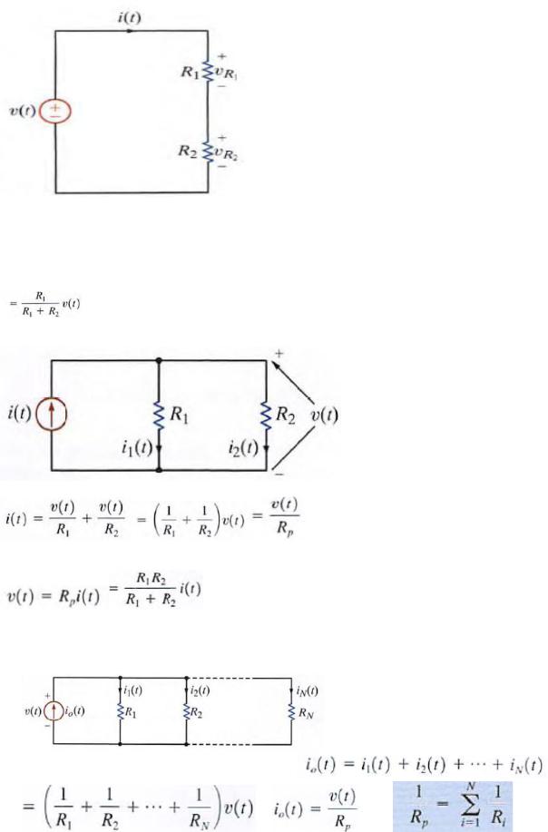
Applying Kirchhoff's voltage law to this circuit yields V(t) = v1, + v2, |
However, from Ohm's law we know that V1, = |
R1i(t) v2 = R2i(t) Therefore,V( t) = R1i(t ) + R2i(t) Solving the equation for i(t) yields  Knowing the
current, we can now apply Ohm's law to determine the voltage across each resistor: V1, = R1i(t )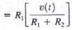
Equations are very important because they describe the operation of what is called a voltage divider. In other words, the source voltage v( t} is divided between the resistors R1 and R2 in direct proportion to their resistances.
Applying Kirchhoff's current law to the upper node, we obtain i(t) = i1(t) + i2(t) and employing Ohm's law, we have
The manner in which the current i(r) from the source divides between the two branches is called current division and can be found from the preceding expressions
and  then
then 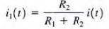
22.Series and parallel resistor combinations.
i.consider the circuit
Now consider the circuit with N resistors in parallel.
Applying Kirchhoff's current law to the upper node yields |
|
or |
where |
23. What are the node voltages in nodal analysis?
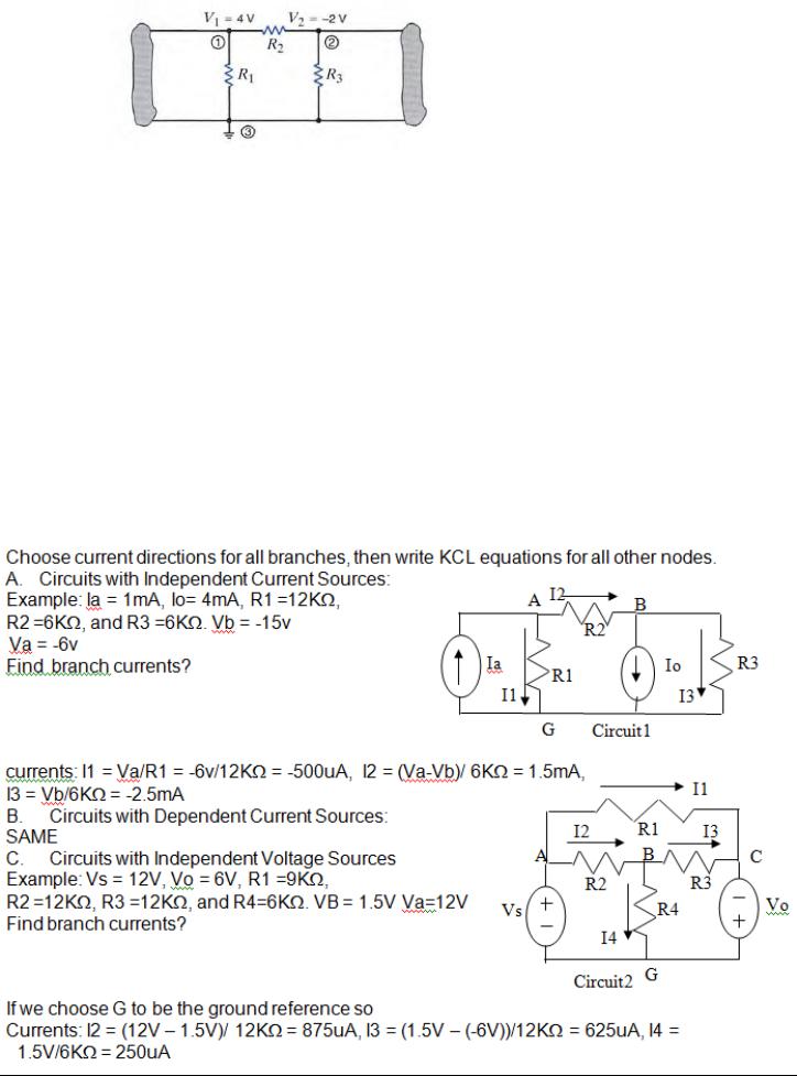
a.
b.The voltage VI = 4 V is the voltage at node 1 with respect to the reference node 3. Similarly. the voltage V2 = - 2 V is the voltage at node 2 with respect to node 3. In addition, however, the voltage at node 1 with respect to node 2 is +6 Y, and the voltage at node 2 with respect to node 1 is - 6 V. Furthermore, since the current will flow from the node of higher potential to the node of lower potential, the current in R1 is from top to bottom, the current in R2 is from left 10 right, and the current in R) is from bottom to top.
24.Reference and nonreference nodes in nodal analysis.
a.In a nodal analysis, the variables in the circuit are selected to be the node voltages. The node voltages are defined With respect to a common point in the circuit. One node is selected as the reference node, and all other node voltages are defined with respect to that node. It is commonly called ground because it is said to be at ground-zero potential. We will select our variables as being positive with respect to the reference node. In a nodal analysis, we employ KCL equations. one of the nodes in an N-node circuit is selected as the reference node, and the voltages at all the remaining N - I nonreference nodes arc measured with respect to this reference node.
25.How to calculate the current through any resistive element knowing the node voltages at its terminals?
26. What is a loop current in loop analysis?
A mesh current is a current that loops around the essential mesh and the equations are set solved in terms of them. A mesh current may not correspond to any physically flowing current, but the physical currents are easily found from them.
27.Describe the algorithm of the nodal analysis for an N-node circuit.
a.Determine the number of nodes in the circuit. Select one node as the reference node. Assign a node voltage between each nonreference node and the reference node. All node Voltages are assumed positive with respect to the reference node. For an N-node circuit, there are N - J node voltages. As a result, N - I linearly independent equations must be written to solve for the node voltages.
b.Write a constraint equation for each voltage source independent or dependentin the circuit in terms of the assigned node voltages using KVL. Each constraint equation represents one of the necessary linearly independent equations, and Nv voltage sources yield Nv linearly independent equations. For each dependent voltage source, express the controlling variable for that source in terms of the node voltages. A voltage source-independent or dependent-may be connected between a nonreference node and the reference node or between two nonreference nodes. A supernode is formed by a voltage source and its two connecting nonreference nodes.
c.Use KCL to formulate the remaining N - I - Nv linearly independent equations. First, apply KCL at each nonreference node not connected to a voltage source. Second, apply KCL at each supernode. Treat dependent current sources like independent current sources when formulating the KCL equations. For each dependent current source, express the controlling variable in tenns of the node voltages.
28.Describe the algorithm of the loop analysis for an N-loop circuit.
a.Determine the number of independent loops in the circuit. Assign a loop current to each independent loop. For an N- Ioop circuit, there are N-loop currents. As a result , N linearly independent equations must be written to solve for the loop current s.
b.If current sources are present in the circuit, either of two techniques can be employed. In the first case, one loop current is selected to pass through one of the current sources.The remaining loop currents are determined by open circuiting the current sources in the circuit and using this modified circuit to select them. In the second case, a current is assigned to each mesh in the circuit.
c.Write a constraint equation for each current source independent or dependentin the circuit in terms of the assigned loop currents using KCL. Each constraint equation represents one of the necessary linearly independent equations, and Nt current sources yield Nt linearly independent equations. For each dependent current source, express the controlling variable for that source in terms of the loop currents.
d.Use KVL t0 formulate the remaining N - N/ linearly independent equations. Treat dependent voltage sources like independent voltage sources when formulating the KVL equations. For each dependent voltage source, express the controlling variable in terms of the loop currents.
29. Capacitor. Capacitance. Current and voltage relationship on capacitor.
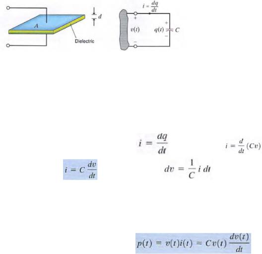
A capacitor is a circuit element that consists of two conducting surfaces separated by a nonconducting, or dielectric, material. There are many different kinds of capacitors, and they are categorized by the type of dielectric material used between the conducting plates.
Capacitance is measured in coulombs per volt or farads. It is interesting to calculate the dimensions of a simple equivalent capacitor consisting of two
parallel plates each of area A, separated by a distance d  , where Eo' the permitivity of free space, is 8.85
X 10- " F / m.
The charge on the capacitor is proportional to the voltage across it such that q = Cv
The charge differential between the plates creates an electric field that stores energy. Because of the presence of the dielectric, the conduction current that flows in the wires that connect the capacitor to the remainder of the circuit cannot flow internally between the plates. However. Via electromagnetic field theory it can be shown that this conduction current is equal to the displacement current that flows between the plates of the capacitor and is present any time that an electric
field or voltage varies with time. (Since the current is |
then for a capacitor |
which for |
|
constant capacitance is |
.eq can be rewritten as |
. Now integrating this expression |
|
from  to some time t and assuming
 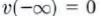 yields
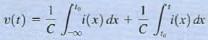
 where V( to) is the voltage due to the charge that accumulates on the capacitor from time
  to time t= t0. The energy stored in the capacitor can be derived from the power that is delivered to
the element. This power is given by the expression |
) |
Derivating wrt time the last equation: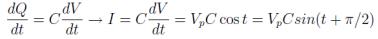
This expression shows us that a constant voltage across a capacitor produces no current through the capacitor. Also we see that current and voltage are not in phase.
30. Describe the case of a dc voltage applied across a capacitor.
 we see that the current flowing through the capacitor is direct ly proportional to the time rate of change of the voltage across the capacitor. A dc voltage does not vary with time, so the current flowing through the capacitor is zero. We can say that a capacitor is "an open circuit to de" or "blocks de." Capacitors are often utilized to remove or filter out an unwanted dc voltage. the power absorbed by a capacitor, is directly proportional to the time rate of change of the voltage across the capacitor. if we had an instantaneous change in the capacitor voltage This would correspond to dv/ dt =
  and infinite power. Since we only have finite power sources, the voltage across a capacitor cannot change instantaneously.

31. Mathematically prove that a capacitor is a passive element.
To determine whether component is passive , the total energy absorbed by it must be greater or equal zero
.the total capacitor energy is . It’s apparent that the total energy of the capacitor will be greater than zero if the capacitance greater than zero. Since the capacitance is dependent on capacitor construction, it cannot be negative. therefore, capacitor is passive element
32. What is an idea of ―continuity of voltage‖ for a capacitor?
the power absorbed by a capacitor, is directly proportional to the time rate of change of the voltage across the capacitor. if we had an instantaneous change in the capacitor voltage This would correspond to dv/ dt =  and infinite power. Since we only have finite power sources, the voltage across a capacitor cannot change instantaneously. This idea of "continuity of voltage for a capacitor tells us that the voltage across the capacitor just after a switch moves is the same as the voltage across the capacitor just before that switch moves.
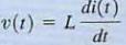
33.Inductor. Inductance. Current and voltage relationship on inductor.
a.An inductor is a circuit element that consists of a conducting wire usually in the form of a coil. An inductor is a device that stores energy in the magnetic field surrounding the inductor. Inductors are typically categorized by the type of core on which they are wound. Inductors made with air or nonmagnetic materials are widely used in radio, television
b.
c.(It was first shown that a current-carrying conductor would produce a magnetic field. it was later found that the magnetic field and the current that produced it were linearly related.. it was shown that a changing magnetic field produced a voltage that was proportional to the time rate of change of the current that produced the magnetic field  The constant of proportionality L is called the inductance and is measured in the unit henry, is dimensionally equal to 1 volt-second per ampere. we find that the expression for the current in an inductor is
 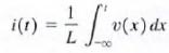 which can also be written as
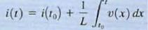
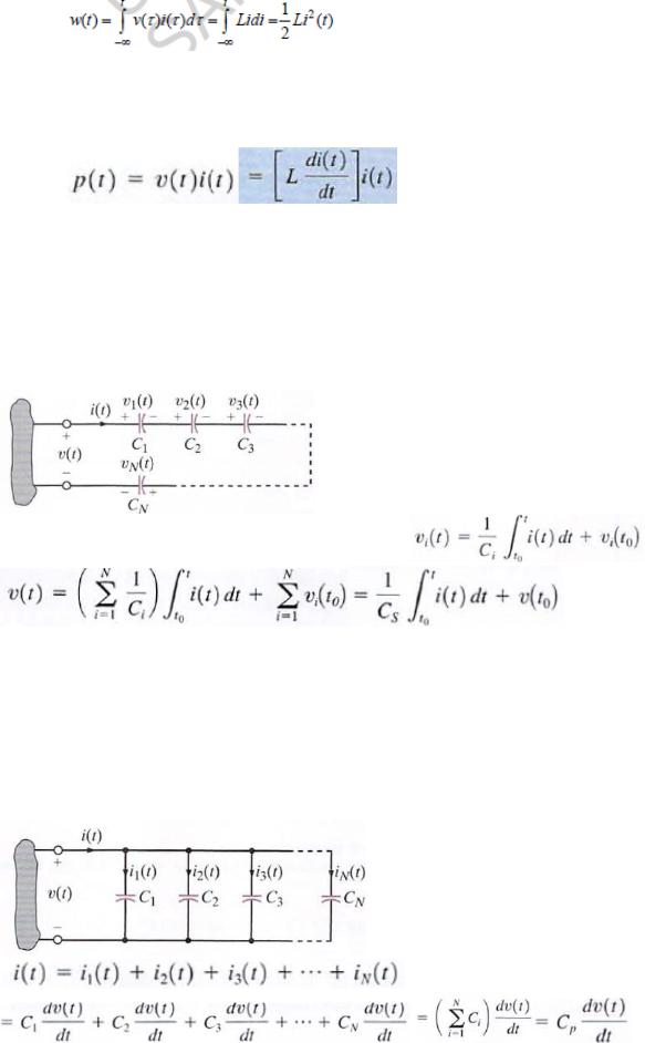
d.The power delivered to the inductor can be used to derive the energy stored in the element. This power is equal to
)
e.We have already seen that from Faraday’s law we obtain:
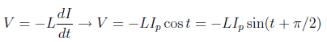 so again voltage and current are not in phase.
34.Describe the case of a dc current flowing through an inductor.
 we see that the voltage across the inductor is direct ly proportional to the time rate of change of the current flowing through the inductor. A dc current does not vary with time,so the voltage across the inductor is zero. We can say that an inductor is "a short circuit to dc." we can replace any inductors with short circuits and calculate voltages and currents in the circuit
35. Mathematically prove that an inductor is a passive element.
The total inductor energy is . Total energy of the inductor will be greater than zero if the inductance greater than zero. Since the inductance cannot be negative, inductor is passive element
36. What is an idea of ―continuity of current‖ for an inductor?
a. Note from that an instantaneous change in inductor current would require in finite power. Since we don' t have any infinite power sources, the current flowing through an inductor cannot change instantaneously. This idea of "continuity of current" for an inductor tells us that the current flowing through an inductor just after a switch moves is the same as the current flowing through an inductor just before that switch moves.
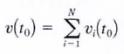
37.Prove that capacitors in series combine like resistors in parallel.
a.If a number of capacitors are connected in series, their equivalent capacitance can be calcu lated using KVL. For this circu it
b.
 but =>
where
 and
and 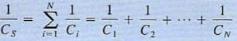
c.since the same current flows in each of the series capacitors, each capacitor gains the same charge in the same time period. The voltage across each capacitor will depend on th is charge and the capacitance of the element
38.Prove that capacitors in parallel combine like resistors in series.
a.To determine the equivalent capacitance of N capacitors connected in parallel. we employ KCL.
b.
c.
d.where
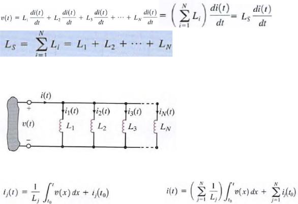
39.Prove that inductors in series combine like resistors in series.
a.If N inductors are connected in series. the equivalent inductance of the combination can be determined as follows. using KVL, we see that
b. 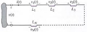 c.
c. 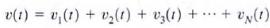 therefore
where
40. Prove that inductors in parallel combine like resistors in parallel.
a.
b.Consider the circuit which contains N parallel inductors. Using KCL, we can write  however
c. |
substituting to 1st eq |
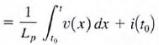 where
where 
41. First-order circuits. Transition period. Steady-state value. Time constant.
An RC or RL transient circuit is said to be first order if it contains only a single capacitor or single inductor. The voltage or current anywhere in the network can be obtained by solving a first-order differential equation.
The function e - 1/1 decays to a value that is less than 1 % of its initial value after a period of ST. Therefore, the time constant, T, determines the time required for the circuit to reach steady state.
The time constant for an RC circuit is RTh C and for an RL circuit is L/RTh , where RTh is the Thevenin equivalent resistance looking into the circuit at the terminals of the storage element (i.e., capacitor or inductor).
42. Second-order circuits. Different techniques for performing a transient analysis.
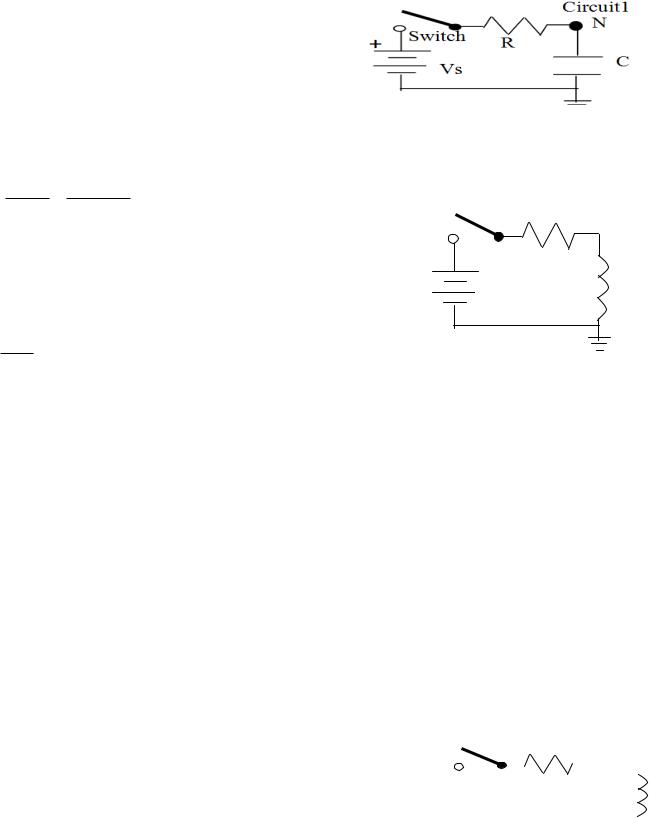
For circuit1, the capacitor has no initial voltage, and
The switch closes at t=0s
For the RC capacitor circuit1 - write a KCL equation.
C dVc(t) Vc(t) Vs 0
dt R
For circuit2, the inductor has no initial current, and The switch closes at t=0s
For the RL inductor circuit2 – write a KVL equation.
|
|
Circuit2 |
+ |
Switch |
R |
|
||
|
Vs |
L |
|
|
L dI (t) R I (t) Vs
dt
t
Use the general form solution for a first order differential equation x(t) K1 K 2 e
For this general form solution: K1 = steady state value (after a long time).
K2 = the initial condition. = the time constant.
Using this general solution in the KCL equation: K1 = Vs, K2 = -Vs, and = R x C Using this general solution in the KVL equation: K1 = Vs / R, K2 = -Vs / R, and = L / R
43.General form of the response equation for the first-order circuit. For circuit1, the switch opens at t=to
For a parallel RLC circuit1 - write a KCL equation.
C |
dV (t) |
|
|
V (t) |
|
1 |
t V (x)dx I L (to) Is(t) |
|
|
|
|
|
|
|
|
|
|
|
|
|
|
|
|
|
|
Circuit2 |
||||||
|
|
|
|
|
|
|
|
|
|
|
|
|
|
|
|
|
|
|
|
|||||||||||||
|
|
dt |
|
|
|
R |
L |
to |
|
|
|
|
|
|
|
|
|
|
|
|
|
|
|
|
|
|
|
|
|
|||
|
|
|
|
|
|
|
|
|
|
|
|
|
|
|
|
|
|
|
|
|
|
|
|
|
|
|||||||
|
|
|
|
|
|
|
|
|
|
|
|
|
|
|
|
|
|
|
|
|
|
|
|
|
|
|
|
|
|
|
|
|
|
|
|
|
|
|
|
|
|
|
|
|
|
|
|
|
|
|
Sw |
|
|
|
|
|
|
|
|
|
|
||||
|
|
|
|
|
|
|
|
|
|
|
|
+ |
|
|
|
|
|
|
|
R |
|
|
|
|
|
|||||||
For circuit2, the switch closes at t=to |
|
|
|
|
|
|
|
|
C |
|||||||||||||||||||||||
|
|
|
|
|
|
|
|
|
|
|
|
|
||||||||||||||||||||
|
|
|
|
|
|
|
|
|
|
|
|
|
|
|
|
|
|
|
|
|
|
|
|
|
|
|
|
|
|
|
L |
|
For series RLC circuit2 – write a KVL equation. |
|
|
|
|
|
|
|
|
|
|
|
Vs |
|
|
|
|
|
|||||||||||||||
|
|
|
|
|
|
|
|
|
|
|
|
|
|
|
|
|
||||||||||||||||
|
|
|
|
|
|
|
|
|
|
|
|
|
|
|
|
|
|
|
|
|
||||||||||||
L |
dI (t) |
|
1 |
t I (x)dx Vc(to) R I (t) Vs(t) |
|
|
|
|
|
|
|
|
|
|
|
|
|
|
|
|
|
|
|
|
|
|||||||
|
|
|
|
|
|
|
|
|
|
|
|
|
|
|
|
|
|
|
|
|
||||||||||||
|
|
|
|
|
|
|
|
|
|
|
|
|
|
|
|
|
|
|
|
|
||||||||||||
|
|
|
|
|
|
|
|
|
|
|
|
|
|
|
|
|
|
|
|
|
||||||||||||
|
|
|
|
|
|
|
|
|
|
|
|
|
|
|
|
|
|
|
|
|
||||||||||||
|
|
|
|
|
|
|
|
|
|
|
|
|
|
|
|
|
|
|
|
|
|
|
|
|
||||||||
|
|
dt |
|
C |
to |
|
|
|
|
|
|
|
|
|
|
|
|
|
|
|
|
|
|
|
|
|
|
|
||||
|
|
|
|
|
|
|
|
|
|
|
|
|
|
|
|
|
|
|
|
|
|
|
|
|
|
|
|
|
|
|
||
Since the initial conditions are constant, taking the derivative of these equations gives equations of the
general form: |
dX 2 (t) |
a |
dX (t) |
a |
|
X (t) f (t) |
|
|
2 |
||||
|
dt 2 |
1 |
dt |
|
||
|
|
|
|
|||