

lyubitelyam_khalyavy PDF
.pdfsource internal resistance intact. Alternatively, you could replace the source with a resistor equal to its internal resistance.
In order to use the superposition theorem with circuit currents and voltages, all of the components must be linear; that is, for all resistive components, the current must be proportional to the applied voltage (satisfying
Ohm’s law).
Note that the superposition theorem is not applicable to power, since power is not a linear quantity. The total power delivered to a resistive component must be determined using the total current through or the total voltage across the component and cannot be determined by a simple sum of the powers produced by the sources independently.
65. Maximum average power transfer.
Sometimes in engineering we are asked to design a circuit that will transfer the maximum power to a load from a given source. According to the maximum power transfer theorem, a load will receive maximum power from a source when its resistance (RL) is equal to the internal resistance (RI) of the source. If the source circuit is already in the form of a Thevenin or Norton equivalent circuit (a voltage or current source with an internal resistance), then the solution is simple. If the circuit is not in the form of a Thevenin or Norton equivalent circuit, we must first use Thevenin’s or Norton’s theorem to obtain the equivalent circuit.
66. Effective or rms values.
The root-mean-square (rms) value or effective value of an ac waveform is a measure of how effective the waveform is in producing heat in a resistance.
Example: If you connect a 5 Vrms source across a resistor, it will produce the same amount of heat as you would get if you connected a 5 V dc source across that same resistor. On the other hand, if you connect a 5 V peak source or a 5 V peak-to-peak source across that resistor, it will not produce the same amount of heat as a 5 V dc source.
That's why rms (or effective) values are useful: they give us a way to compare ac voltages to dc voltages.
To show that a voltage or current is an rms value, we write rms after the unit: for example, Vrms = 25 V rms.
67. Apparent power. Power factor.
The power factor of an AC electrical power system is defined as the ratio of the real power flowing to the load to the apparent power in the circuit,[1][2] and is a dimensionless number between 0 and 1. Real power is the capacity of the circuit for performing work in a particular time. Apparent power is the product of the current and voltage of the circuit. Due to energy stored in the load and returned to the source, or due to a non-linear load that distorts the wave shape of the current drawn from the source, the apparent power will be greater than the real power.
In an electric power system, a load with a low power factor draws more current than a load with a high power factor for the same amount of useful power transferred. The higher currents increase the energy lost in the distribution system, and require larger wires and other equipment. Because of the costs of larger equipment and wasted energy, electrical utilities will usually charge a higher cost to industrial or commercial customers where there is a low power factor.
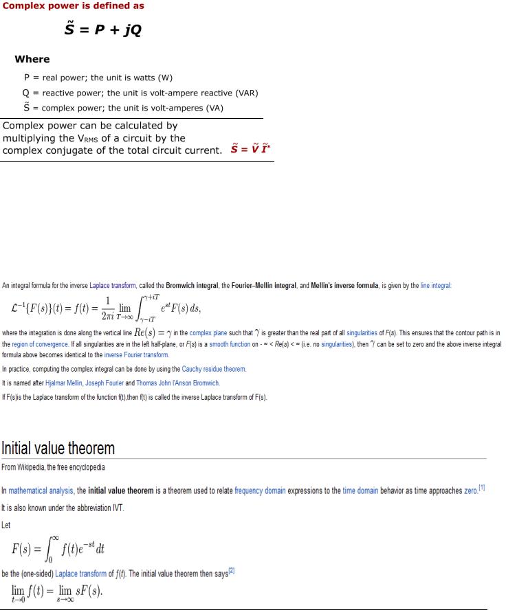
68. Complex power.
69. The Laplace transform. The inverse Laplace transform. Give an example of transform pair.
The Laplace transform is a widely used integral transform with many applications in physics and engineering.
Denoted  , it is a linear operator of a function f(t) with a real argument t (t ≥ 0) that transforms it to a function F(s) with a complex argument s. This transformation is essentially bijective for the majority of practical uses; the respective pairs of f(t) and F(s) are matched in tables. The Laplace transform has the useful property that many relationships and operations over the originals f(t) correspond to simpler relationships and operations over the images F(s).
70. The initial-value theorem. The final-value theorem.
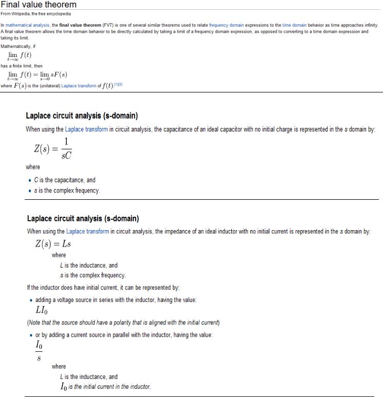
71. The s-domain equations for the capacitor.
72. The s-domain equations for the inductor.
73.Transfer (network) function. Importance of transfer function. Relationship between the roots of characteristic equation for the natural response of a second-order network and transfer function.
a.It is essentially nothing more than the ratio of some output variable to some input variable. if both variables are voltages, the transfer function is a voltage gain. If both variables are currents, the transfer function is a current gain. If one variable is a voltage and the other is a current, the transfer function becomes a transfer admittance or impedance. if only a single storage element is present, the natural response of a network to an initial condition is always of the form x( t ) = X0e-t/τ where x(t) can be either v(t) or i(t), X0 is the initial value of X(t). and T is the time constant of the network. We also found that the natural response of n second-order network is controlled by the roots of the characteristic equation, which is of the form
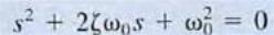 where ζ is the damping ratio and w0 is the undamped natural frequency
b.Case 1, ζ >1: Overdamped Network The roots of the characteristic equation are 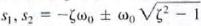 and, therefore, the network response is of the form
c.Case 2, ζ < 1: Underdamped Network The roots of the characteristic equation are 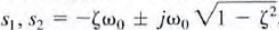 and, therefore . the network response is of the form
d.Case 3, ζ=1: Critically Damped Network The roots of the characteristic equation are  and, hence, the response is of the form
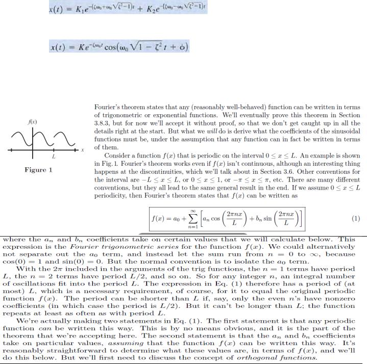
74.How to express any periodic function as a sum of sinusoidal functions? Fourier series.
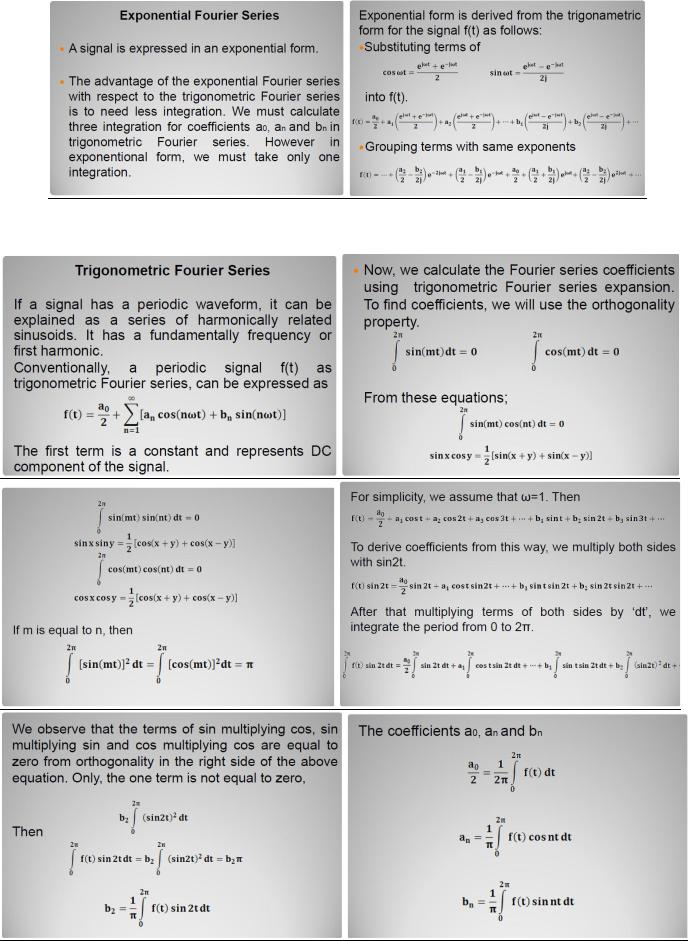
75. Exponential Fourier series.
76. Trigonometric Fourier series.
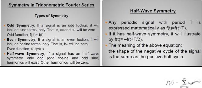
77. Symmetry and the trigonometric Fourier series.
78. Examine the effect of time-shifting a periodic waveform defined by the exponential Fourier series.
i. the effect of time-shifting a periodic waveform f(t ) defined by the equation |
Note |
that 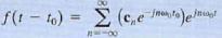 Since e -jnw0t0 corresponds to a phase shift, the Fourier coefficients of the time-shifted function are the Fourier coefficients of the original function, with the angle shifted by an amount directly proportional to frequency. Therefore, time shift in the time domain corresponds to phase shift in the frequency domain. we can compute the phase shift in degrees using
the expression 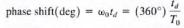
79. Frequency spectrum.
The frequency spectrum of a time-domain signal is a representation of that signal in the frequency domain. The frequency spectrum can be generated via a Fourier transform of the signal, and the resulting values are usually presented as amplitude and phase, both plotted versus frequency.
Any signal that can be represented as an amplitude that varies with time has a corresponding frequency spectrum. This includes familiar concepts such as visible light (color), musical notes, radio/TV channels, and even the regular rotation of the earth. When these physical phenomena are represented in the form of a frequency spectrum, certain physical descriptions of their internal processes become much simpler. Often, the frequency spectrum clearly shows harmonics, visible as distinct spikes or lines, that provide insight into the mechanisms that generate the entire signal.
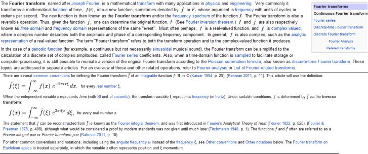
80. The Fourier transform. The inverse Fourier transform. Give an example of transform pair.
81.The principle of superposition.
The Superposition Principle states that in any linear network composed of resistors and voltage sources, the voltage across a resistor is simply the sum of all the voltages individually applied to it by each voltage source in the circuit. The superposition principle is a useful method for finding the voltage across any resistor in a network where more than one voltage source is present. A voltage source in this context may refer to any source of voltage or voltage signal, e.g., power supplies, batteries, oscillators, signal generators, etc.
82.Thevenin’s theorem.
In circuit theory, Thévenin's theorem for linear electrical networks states that any combination of voltage sources, current sources, and resistors with two terminals is electrically equivalent to a single voltage source V and a single series resistor R. For single frequency AC systems the theorem can also be applied to general impedances, not just resistors. This theorem states that a circuit of voltage sources and resistors can be converted into a Thévenin equivalent, which is a simplification technique used in circuit analysis. The Thévenin equivalent can be used as a good model for a power supply or battery (with the resistor representing the internal impedance and the source representing the electromotive force). The circuit consists of an ideal voltage source in series with an ideal resistor.
83. Norton’s theorem.
Norton's theorem for linear electrical networks, known in Europe as the Mayer–Norton theorem, states that any collection of voltage sources, current sources, and resistors with two terminals is electrically equivalent to an ideal current source, I, in parallel with a single resistor, R. For single-frequency AC systems the theorem can also be applied to general impedances, not just resistors. The Norton equivalent is used to represent any network of linear sources and impedances, at a given frequency. The circuit consists of an ideal current source in parallel with an ideal impedance (or resistor for non-reactive circuits).
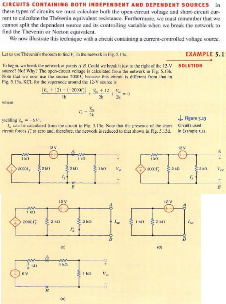
84.How to calculate the Thevenin’s equivalent resistance in the circuits that contain both independent and dependent sources?

85. Source transformation.
Finding a solution to a circuit can be somewhat difficult without using tricks or methods that make the circuit appear simpler. Circuit solutions are often simplified, especially with mixed sources, by transforming a voltage into a current source, and vice versa. This process is known as a source transformation, and is an application of Thevenin's theorem and Norton's theorem.
Performing a source transformation consists of using Ohms Law to take an existing voltage source in series with a resistance, and replace it with a current source in parallel with the same resistance. Remember that Ohms law states that a voltage in a material is equal to the material's resistance times the amount of current through it (V=IR). Since source transformations are bilateral, one can be derived from the other. Source transformations are not limited to resistive circuits however. They can be performed on a circuit involving capacitors and inductors, as long as the circuit is first put into the frequency domain. In general, the concept of source transformation is an application of Thevenin's theorem to a current source, or Norton's theorem to a voltage source.