

lyubitelyam_khalyavy PDF
.pdfThe homogeneous form: |
dX 2 (t) |
a |
dX (t) |
a |
|
X (t) 0 |
|
|
2 |
||||
|
dt 2 |
1 |
dt |
|
||
|
|
|
|
|||
44.Describe the differential equation approach.
a.Equation 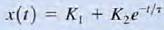 defines the general form of the solution of first-order transient circuits; that is, it represents the solution of еhe differential equation that describes an unknown current or voltage anywhere in the network
Consider the circuit
capacitor voltage for time t > of the form V(t)=K1+K2 e-t/τ
At time t = 0, the switch closes. The KCL equation that describes the
0 is  we assume that the solution of this first-order differential equation is Substituting this solution into the differential equation yields
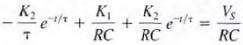 Equaling the constant and exponential terms, we obtain K1= Vs τ= RC
Therefore,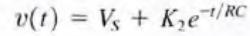 K2 is determined by the initial condition of the capacitor
45.Describe the step-by-step approach.
a.Step 1. We assume a solution for the variable X(t) of the form X(t) = K, + K, e-t/τ
b.Step 2. Assuming that the original circuit has reached steady state before a switch was thrown, draw this
previous circuit with the capacitor replaced by an open circuit or the inductor replaced by a short circuit. Solve for the voltage across the capacitor, vc(o-), or the current through the inductor, iL(o- ), prior to switch action.
c. Step 3. Draw the circuit valid for t = 0+ with the switches in their new positions. Replace a capacitor with a voltage source vc(O+) = vc(o-) or an inductor with a current source of value iL(O+) = iL(o-). Solve for the initial value of the variable x(o+ ).
d. Step 4. Assuming that steady state has been reached after the switches are thrown, draw the equivalent circuit, valid for t > 5τ, by replacing the capacitor by an open circuit or the inductor by a short circuit. Solve for
the steady-state value of the variable 
e.Step 5. Since the time constant for all voltages and currents in the circuit will be the same, it can be obtained
by reducing the entire circuit to a simple series circuit containing a voltage source, resistor, and a storage element (i.e., capacitor or inductor) by forming a simple Thevenin equivalent circuit at the terminals of the storage element. This Thevenin equivalent circuit is obtained by looking into the circuit from the terminals of the storage element. The time constant for a circuit containing a capacitor is T = RTh C, and for a circuit containing an inductor it is t = L/ RTh –
f.Step 6. we can evaluate the constants in step 1 as x(O+) = K, + K, 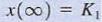 Therefore,
 , and hence the solution is
46. Unit step function. Application of unit step function to circuit analysis.
The unit step function u(t) was defined as |
corresponds to |
closing |
|
a switch at t = 0 and connecting a voltage source of I V or a current source of 1 A to a given circuit. |
|
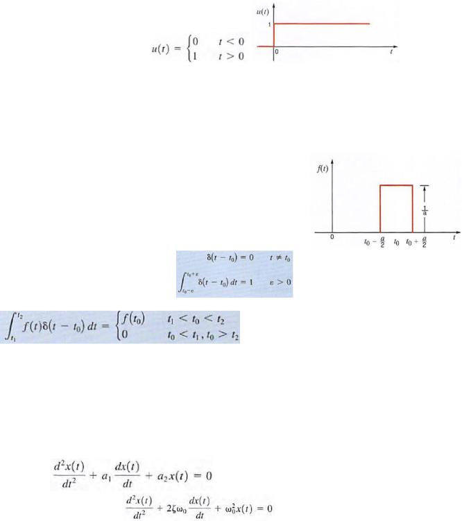
47. Unit impulse function. Application of unit impulse function to circuit analysis.
The unit impulse function can be represented in the limit by the rectangular pulse
as a -> 0. The function is defined by the following The unit impulse is zero except at t = t0, where it is undefined, but it has unit area. An important propert y of the unit impulse function is what is often called the sampling
property, which is exhibited by the following integral for a finite to and any f(t) continuous at t0, Note that the unit impulse function simply samples the value of f(t) at t = t0
48.General form of the response equation for the second-order circuit.
a.a general rule, for this case we are confronted with an equation of the form 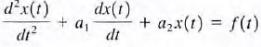 for homogeneous system
all t. Again we assume that 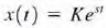 substituting yields
Dividing both sides of the equation by Kest yields This equation is commonly called the characteristic equation ζ is called the exponential damping ratio, and w0 is referred to as the undamped natural frequency.
49. Overdamped form of the unforced response.
ζ> 1 The natural frequencies s1 and s2 are real and unequal; therefore, the natural response of the network described by the second-order differential equation is of the form
 where K1 and K2 are found from the initial conditions. This indicates that the natural response is the sum of two decaying exponentials.
Underdamped form of the unforced response. a. ζ<1
 where A1 and A2, like K1 and K2 are constants. which are evaluated using the initial conditions x(O) and dx(O) / dt. This illustrates that the natural response is an exponentially dampedoscillatory response.
Critically damped form of the unforced response.
ζ=1 results in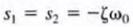 In the case where the characteristic equation has repeated roots, the general
solution is of the form  where BI and B2 are constants derived from the initial conditions.
50.Underdamped form of the unforced response.
a. ζ<1 the natural frequencies are complex numbers. The natural response is then of the form
 where A1 and A2, like K1 and K2 are constants. which are evaluated using the initial conditions x(O) and dx(O) / dt. This illustrates that the natural response is an exponentially dampedoscillatory response.
51. Critically damped form of the unforced response
ζ=1 results in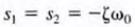 In the case where the characteristic equation has repeated roots, the general solution
is of the form 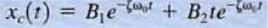 where BI and B2 are constants derived from the initial conditions.
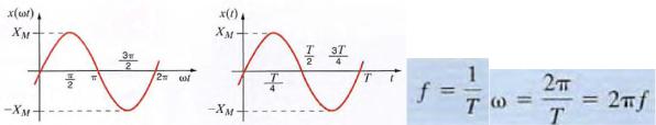
52. General expression for a sinusoidal function. Amplitude. Angular frequency. Period. Phase.
a. X(t ) = Xm sin wt where X(t) could represent either v{t) or i(t). Xm is the amplitude, maximum value or peak value, w is the angular frequency, and wt is the argument of the sine function
b.X[w(t + T)] = X(wt)
c.
let us consider the following general expression for a sinusoidal function: X(t) = Xm sin (wt+ϴ) In this case (WI + 8) is the
argument of the sine function, and ϴ is called the phase angle.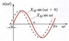 Because of the presence of the phase angle, any point on the waveform

Xmsin(wt + ϴ) occurs ϴ radians earlier in time than the corresponding point on the waveform Xmsinwt . Therefore, we say that Xmsinwt lags Xmsin (Wt + ϴ) by ϴ radians.
53. Three conditions that must be satisfied before determining the phase difference.
54. How to establish a relationship between time-varying sinusoidal functions and complex numbers.

55.Phasors. Phasor analysis. Time domain. Frequency domain.
A phasor is a tool to relate the amplitude of a wave to the phase of a wave. For example, if you remove the time dependence from a sin wave and just look at the spatial dependence, and you write it in phasor form, you can say I(r) = A*exp{-jkr} where A is the wave's amplitude, r, the direction of propagation, k the propagation constant. Now, if you map this in polar form (the phase, phi, is simply k*r), you'll get a circle, where you can say the y-axis represent imaginary space, and the x-axis real space. You can then see as you trace around the circle, and look at the projection onto the real axis (x-axis), the amplitude grows and shrinks as you go around the circle. In fact, if you were to plot this changing in amplitude vs. space, you'd just get a sin wave.
A phasor is a polar representation of a complex number. Instead of real and imaginary components, you have a magnitude and a phase angle.
If the phase angle varies linearly with time, that is precisely the mapping into the frequency domain. (a 4 Hz phasor will have its phase rotate by 360 degrees every quarter of a second)
Also, (in communication theory) instantaneous frequency is just the time derivative of the phase.
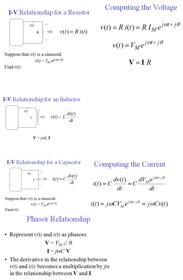
56. Phasor relationship for a resistor.
57. Phasor relationship for an inductor.
58. Phasor relationship for a capacitor.

59. Impedance and admittance.
Impedance (Z) is the over-all measure of the ability of a circuit to resist the flow of alternating current under a given a.c. voltage excitation. It may be expressed as Z = V / I where V and I are the a.c. voltage applied to and current flowing through the circuit. Its unit of measurement is the ohm (volt/ampere).
Admittance (Y) is the reciprocal of reactance, i.e., Y = 1 / Z. The unit of measurement for admittance is the siemens (S).

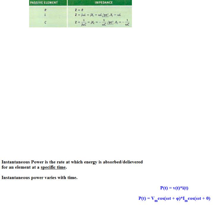
60. Impedances for different passive elements.
a.
61. Resistance. Reactance. Conductance. Susceptance.
If you studied Resistance, Reactance, and Impedance, then you have a pretty good start in the basics of opposition to electric current. However, these three forces each have a twin, which is essentially their opposite. While resistance, reactance, and impedance all tend to restrict how much electricity can flow through a certain path, conductance, susceptance, and admittance are all forces that tend to allow electricity to flow. And there's good news: All of these forces are quite easy to understand and mathematically calculate.
Conductance is the opposite of resistance. While resistance is the restriction of current because of the chemical composition of a substance, conductance is the ability to conduct electricity of a certain material. Conductance is measured in siemens (S). Conductance is the reciprocal of resistance; That is to say, conductance is 1 divided by resistance. For example, if you have a 1,000 ohm resistor, its conductance is 1 divided by 1000, or 0.001 siemens. (This would probably be expressed by an engineer as 1 mS, one millisiemen.) The conductance of a 470 ohm resistor is about 2.13 mS. Notice that as resistance goes down, conductance goes up. Conductance's electrical symbol is G.
62. Instantaneous power.

63. Average power.
The average over time of a modulated signal. The average power (often simply called "power" when the context makes it clear) is the average amount of work done or Energy transferred per unit time. Fiber optic power meters are instruments that measure the average power of a continuous Light beam. They are used to test signal power in fiber optic networks.
64. Superposition is not applicable to power. Why?
The superposition theorem states that in a linear circuit with several sources, the current and voltage for any element in the circuit is the sum of the currents and voltages produced by each source acting independently.
To calculate the contribution of each source independently, all the other sources must be removed and replaced without affecting the final result. When removing a voltage source, its voltage must be set to zero, which is equivalent to replacing the voltage source with a short circuit. When removing a current source, its current must be set to zero, which is equivalent to replacing the current source with an open circuit.
When you sum the contributions from the sources, you should be careful to take their signs into account. It is best to assign a reference direction to each unknown quantity, if it is not already given. The total voltage or current is calculated as the algebraic sum of the contributions from the sources. If a contribution from a source has the same direction as the reference direction, it has a positive sign in the sum; if it has the opposite direction, then a negative sign.
Note that If the voltage or current sources have internal resistance, it must remain in the circuit and still be considered. In TINA, you can assign an internal resistance to the DC voltage and current sources, while using the same schematic symbol. Therefore, if you want to illustrate the superposition theorem and at the same time use sources with internal resistance, you should only set the source voltage (or current) to zero, which leaves the