

4.2. Shore supply
Where arrangements are made for the supply of electricity from a source onshore or other external source, the following requirements apply.
Connection Box and Cable
A shore connection box is to be provided on the vessel for the reception of the flexible cable from an external source. Fixed cables of adequate rating are to be provided between the shore connection box and the main or emergency switchboard.
The cable is to be protected by fuses or a circuit breaker located at the connection box. Where fuses are used, a disconnecting means is also to be provided. Trailing cable is to be appropriately fixed to avoid its imposing excessive stress on the cable terminal.
Interlock Arrangements
An interlocking arrangement is to be provided between all generators, including the emergency generator, and the shore power supply to prevent the shore power from being inadvertently paralleled with the shipboard power.
Instrumentation
An indicator light is to be provided at the main or emergency switchboard to which shore power is connected to show energized status of the cable. Means are to be provided for checking the polarity (for DC) or the phase sequence (for three-phase AC) of the incoming supply in relation to the vessel's system.
Earth Connection
An earth terminal is to be provided for connecting the hull to an external earth.
Information Plate
An information plate is to be provided at or near the connection box giving full information on the system of supply and the nominal voltage (and frequency if AC) of the vessel's system and the recommended procedure for carrying out the connection.
Shore supply is generally required so that the ship's generators and their prime movers can be shut down for major overhaul during a dry docking period. It must also be remembered that the engine generator cooling is in most cases impossible whilst the ship is in a dry dock.
The connection box to connect the shore supply cable is often located at the entrance to the accommodation or in the emergency generator room.
The connection box must have suitable terminals to accept the shore supply cable, including an earthing terminal to connect the ship's hull to the shore's earth point (Refer Figure 4.4). It must have a circuit-breaker or a switch and fuses to protect the cable linking the connection box to the main switchboard, with a data plate depicting details of the ship's electrical system (voltage and frequency), including the method for connecting the shore apply cable.
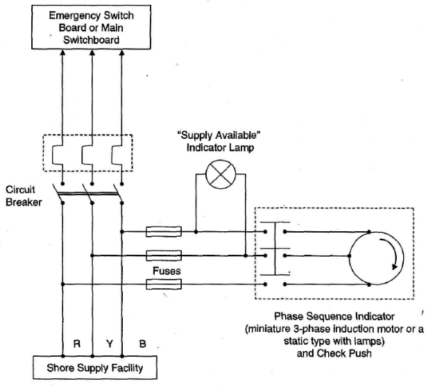
Figure 4.4 - Shore Supply Arrangement
A voltmeter is fitted to indicate polarity of a direct current shore supply. For an alternating current shore supply, a phase sequence indicator is fitted to indicate the correct phase sequence of the supply. The phase-sequence indicator shown in the figure is a rotating type (the dial is shown in Figure 9.40) and is basically a simple miniature 3-phase induction motor; this can be replaced by a static type as shown in Figure 9.41. At the main switchboard an indicator is provided, usually a lamp, to indicate that the shore supply is available. Connection to the bus bars is established via a connecting switch or circuit breaker. It is not normally possible to parallel the shore supply with the ship's generators. In fact it must never be done!
The ship's generators must, therefore, be disconnected before the shore supply can be connected to the main switchboard or emergency switchboard as the case may be. Normally, the shore supply switch on the main switchboard is interlocked with the generator supply breakers so that it cannot be closed if the generators are still connected.
When the shore supply cable is connected and energised, the phase sequence indicator, when operated may indicate a reversed phase sequence. It should be remembered that an incorrect phase sequence will cause the ship's motors to run in the reverse direction - with disastrous results! This is overcome by interchanging any two leads of the shore supply cable at the connection box. While doing so, always ensure that the shore supply in cut-off. The power supply from ashore may have a different voltage and / or frequency to that of the ship's requirements:
Effect of Change in Supply Voltage on Torque and Speed
Torque at any speed is proportional to the square of the applied voltage. If the stator voltage decreases by 10%, the torque decreases by 20%. Changes in supply voltage not only affect the starting torque Tst but also torque under running conditions. If voltage V decreases, then torque T also decreases. Hence, for maintaining the same torque, slip s increases (the speed falls).
The practical difficulties are:
Running at Reduced Voltage (e.g., 440V-rated and running at 380V)
Starting and maximum torque will be low. Thus, a longer acceleration period will be needed and this will result in overheating while starting.
The current will be higher in order to maintain the same power output. Therefore heating occurs while running.
Ageing of insulation will be accelerated due to over-heating
Running at Increased Voltage (e.g., 380V-rated and running at 440V)
Increased voltage drop while starting will probably make lights flicker.
The starting and maximum torque will be increased resulting in a possible shearing of the coupling.
Starting currents will be higher.
Increased motor current at same power will cause over-heating.
Ageing of insulation will be accelerated due to over-heating.
The power factor will be low.
Running at Reduced Frequency (e.g., 60Hz-rated and running at 50Hz)
The current must be increased to generate the same torque.
In order to avoid excessive current, the voltage must be reduced.
The motor runs 20% slower.
Motor cooling by its built-in fan, running at lower speed, is affected; the motor overheats.
Running at Increased Frequency (e.g., 50Hz-rated and running at 60Hz)
The motor runs 20% faster.
The starting torque is reduced.
For blowers and centrifugal pumps, the load increases drastically for a slight increase in speed.
The motor overheats.
Ageing of insulation will be accelerated due to over-heating.