

AIR TRAFFIC CONTROL
.pdf310 |
AIR TRAFFIC CONTROL 11 DEC 09 |
ICAO RULES OF THE AIR – ANNEX 2
5.3RULES APPLICABLE TO IFR FLIGHTS OUTSIDE CONTROLLED AIRSPACE
5.3.1Cruising Levels
An IFR flight operating in level cruising flight outside of controlled airspace shall be flown at a cruising level appropriate to its track as specified in:
a.the Tables of cruising levels in Appendix 3, except when otherwise specified by the appropriate ATS authority for flight at or below 900m (3000 ft) above mean sea level; or
b.a modified table of cruising levels, when so prescribed in accordance with Appendix 3 for flight above FL410.
NOTE: This provision does not preclude the use of cruise climb techniques by aircraft in supersonic flight.
5.3.2Communications
An IFR flight operating outside controlled airspace but within or into areas, or along routes, designated by the appropriate ATS authority in accordance with 3.3.1.2c. or d., shall maintain an air-ground voice communication watch on the appropriate communication channel and establish two-way communication, as necessary, with the air traffic services unit providing flight information service.
NOTE: See Note following 3.6.5.1.
5.3.3Position Reports
An IFR flight operating outside controlled airspace and required by the appropriate ATS authority to:
–submit a flight plan;
–maintain an air-ground voice communication watch on the appropriate communication channel and establish two-way communication, as necessary, with the air traffic services unit providing flight information service;
shall report position as specified in 3.6.3 for controlled flights.
NOTE: Aircraft electing to use the air traffic advisory service whilst operating IFR within specified advisory airspace are expected to comply with the provisions of 3.6, except that the flight plan and changes thereto
are not subjected to clearances and that two-way communication will be maintained with the unit providing the air traffic advisory service.
APPENDIX 1 — SIGNALS
NOTE: See Chapter 3, para 3.4 of the Annex.
1DISTRESS AND URGENCY SIGNALS
See EMERGENCY Section for complete information.
NOTE: None of the provisions contained in the Emergency Section shall prevent the use, by an aircraft in distress, of any means at its disposal to attract attention, make known its position and obtain help.
2SIGNALS FOR USE IN THE EVENT OF INTERCEPTION
See EMERGENCY Section for complete information.
3VISUAL SIGNALS USED TO WARN AN UNAUTHORIZED AIRCRAFT FLYING IN, OR ABOUT TO ENTER A RESTRICTED, PROHIBITED
OR DANGER AREA
By day and by night, a series of projectiles discharged from the ground at intervals of 10 seconds, each showing, on bursting, red and green lights or stars will indicate to an unauthorized aircraft that it is flying in or about to enter a restricted, prohibited or danger area, and that the aircraft is to take such remedial action as may be necessary.
4SIGNALS FOR AERODROME TRAFFIC
4.1LIGHT AND PYROTECHNIC SIGNALS
4.1.1Instructions
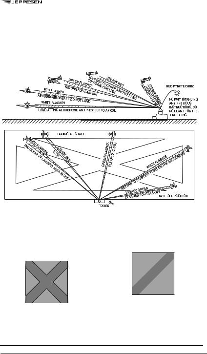
Light signals are directed from Aerodrome Control to aircraft concerned. (See Figure 4-1.)
4.1.2 Acknowledgment by an Aircraft —
a.When in flight:
1.during the hours of daylight:
– by rocking the aircraft’s wings;
NOTE: This signal should not be expected on the base and final legs of the approach.
© JEPPESEN, 1999, 2009. ALL RIGHTS RESERVED.
11 DEC 09 AIR TRAFFIC CONTROL |
311 |
ICAO RULES OF THE AIR – ANNEX 2
2.during the hours of darkness:
–by flashing on and off twice the aircraft’s landing lights or, if not so equipped, by switching on and off twice its navigation lights.
b.When on the ground:
1.during the hours of daylight:
–by moving the aircraft’s ailerons or rudder;
2.during the hours of darkness:
–by flashing on and off twice the aircraft’s landing lights or, if not so equipped, by switching on and off twice its navigation lights.
Figure 4-1 (see 4.1.1)
4.2VISUAL GROUND SIGNALS
NOTE: For details of visual ground aids, see Annex 14 (not published herein).
4.2.1Prohibition of Landing
A horizontal red square panel with yellow diagonals when displayed in a signal area indicates that landings are prohibited and that the prohibition is liable to be prolonged.
4.2.2Need for Special Precautions While Approaching or Landing
A horizontal red square panel with one yellow diagonal when displayed in a signal area indicates that owing to the bad state of the manoeuvring area, or for any other reason, special precautions must be observed in approaching to land or in landing.
4.2.3Use of Runways and Taxiways
4.2.3.1 A horizontal white dumb-bell when displayed in a signal area indicates that aircraft are required to land, take-off and taxi on runways and taxiways only.
© JEPPESEN, 1999, 2009. ALL RIGHTS RESERVED.

312 |
AIR TRAFFIC CONTROL 11 DEC 09 |
ICAO RULES OF THE AIR – ANNEX 2
4.2.3.2 The same horizontal white dumb-bell as in 4.2.3.1 but with a black bar placed perpendicular to the shaft across each circular portion of the dumbbell when displayed in a signal area indicates that aircraft are required to land and take-off on runways only, but other manoeuvres need not be confined to runways and taxiways.
4.2.6Right-Hand Traffic
When displayed in a signal area, or horizontally at the end of the runway or strip in use, a right-hand arrow of conspicuous color indicates that turns are to be made to the right before landing and after take-off.
4.2.4Closed Runways or Taxiways
Crosses of a single contrasting color, yellow or white, displayed horizontally on runways and taxiways or parts thereof indicate an area unfit for movement of aircraft.
4.2.5Directions for Landing or Take-off
4.2.5.1 A horizontal white or orange landing T indicates the direction to be used by aircraft for landing and take-off, which shall be in a direction parallel to the shaft of the T towards the cross arm.
4.2.7Air Traffic Services Reporting Office
The letter C displayed vertically in black against a yellow background indicates the location of the air traffic services reporting office.
4.2.8Glider Flights in Operation
A double white cross displayed horizontally in the signal area indicates that the aerodrome is being used by gliders and that glider flights are being performed.
NOTE: When used at night, the landing T is either illuminated or outlined in white colored lights.
4.2.5.2 A set of two digits displayed vertically at or near the aerodrome control tower indicates to aircraft on the manoeuvring area the direction for take-off, expressed in units of 10 degrees to the nearest 10 degrees of the magnetic compass.
5 MARSHALLING SIGNALS
5.1FROM A SIGNALMAN TO AN AIRCRAFT
NOTE 1: These signals are designed for use by the signalman, with hands illuminated as necessary to facilitate observation by the pilot, and facing the aircraft in a position:
a)for fixed wing aircraft: on left side of aircraft where best seen by the pilot; and
b)for helicopters: where the signalman can best be seen by the pilot.
NOTE 2: The meaning of the relevant signals remains the same if bats, illuminated wands or torchlights are held.
NOTE 3: The aircraft engines are numbered for the signalman facing the aircraft, from right to left (i.e., No.1 engine being the port outer engine).
NOTE 4: Signals marked with an asterisk are designed for use by hovering helicopters.
NOTE 5: References to wands may also be read to refer to daylight-fluorescent table-tennis bats or gloves (daytime only).
© JEPPESEN, 1999, 2009. ALL RIGHTS RESERVED.
11 DEC 09 AIR TRAFFIC CONTROL |
313 |
ICAO RULES OF THE AIR – ANNEX 2
5.1.1 Prior to using the following signals, the signalman shall ascertain that the area within which an aircraft is to be guided is clear of objects which the aircraft, in complying with 3.4.1, might otherwise strike.
NOTE: The design of many aircraft is such that the path of the wing tips, engines and other extremities cannot always be monitored visually from the flight deck while the aircraft is being manoeuvred on the ground.
5.1.1.1Wingwalker/guide
Raise right hand above head level with wand pointing up; move left-had wand pointing down toward body.
NOTE: This signal provides an indication by a person positioned at the aircraft wing tip, to the pilot/marshaller/push-back operator, that the aircraft movement on/off a parking position would be unobstructed.
5.1.1.2Identify Gate
Raise fully extended arms straight above head with wands pointing up.
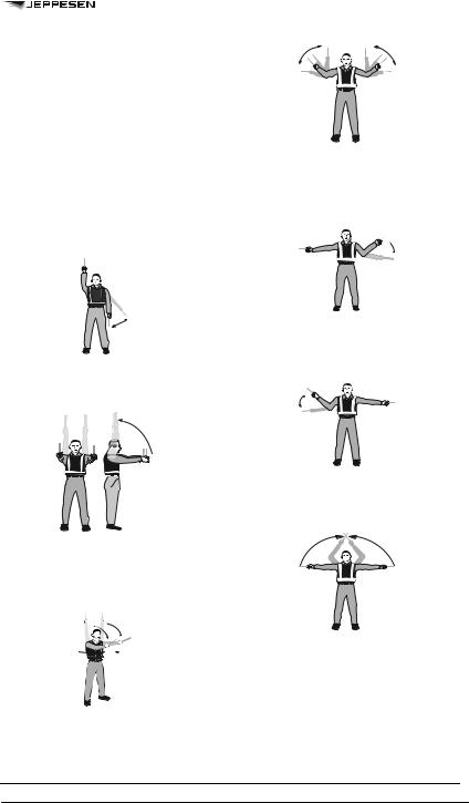
5.1.1.3Proceed To Next Signalman or as Directed by Tower/Ground Control
Point both arms upward; move and extend arms outward to sides of body and point with wands to direction of next signalman or taxi area.
5.1.1.5Turn
a)Turn left (from pilot’s point of view): With right arm and wand extended at a 90-degree angle to body, make “come ahead” signal with left hand. The rate of signal motion indicates to pilot the rate of aircraft turn.
b)Turn right (from pilot’s point of view): With left arm and wand extended at a 90-degree angle to body, make “come ahead” signal with right hand. The rate of signal motion indicates to pilot the rate of aircraft turn.
5.1.1.6Stop
a)Normal stop: Fully extend arms and wands at a 90-degree angle to sides and slowly move to above head until wands cross.
b)Emergency stop: Abruptly extend arms and wands to top of head, crossing wands.
5.1.1.4Straight Ahead
Bend extended arms at elbows and move wands up and down from chest height to head.
© JEPPESEN, 1999, 2009. ALL RIGHTS RESERVED.

314 |
AIR TRAFFIC CONTROL 11 DEC 09 |
ICAO RULES OF THE AIR – ANNEX 2
5.1.1.7Brakes
a)Set brakes: Raise hand just above shoulder height with open palm. Ensuring eye contact with flight crew, close hand into a fist. Do not move until receipt of “thumbs up” acknowledgement from flight crew.
b)Release brakes: Raise hand just above shoulder height with hand closed in a fist. Ensuring eye contact with flight crew, open palm. Do not move until receipt of “thumbs up” acknowledgement from flight crew.
5.1.1.8Chocks
a)Chocks inserted: With arms and wands fully extended above head, move wands inward in a “jabbing” motion until wands touch. Ensure acknowledgement is received from flight crew.
b)Chocks removed: With arms and wands fully extended above head, move wands outward in a “jabbing” motion. Do not remove chocks until authorized by flight crew.
5.1.1.9Start Engine(s)
Raise right arm to head level with wand pointing up and start a circular motion with hand; at the same time, with left arm raised above head level, point to engine to be started.
5.1.1.10Cut Engines
Extend arm with wand forward of body at shoulder level; move hand and wand to top of left shoulder and draw wand to top of right shoulder in a slicing motion across throat.
5.1.1.11Slow Down
Move extended arms downwards in a “patting” gesture, moving wands up and down from waist to knees.
5.1.1.12Slow Down Engine(s) on Indicated Side
With arms down and wands toward ground, wave either right or left wand up and down indicating engine(s) on left or right side respectively should be slowed down.
© JEPPESEN, 1999, 2009. ALL RIGHTS RESERVED.

11 DEC 09 AIR TRAFFIC CONTROL |
315 |
ICAO RULES OF THE AIR – ANNEX 2
5.1.1.13Move Back
With arms in front of body at waist height, rotate arms in a forward motion. To stop rearward movement, use signal 5.1.1.6 a) or b).
5.1.1.14Turns While Backing
a)For tail to starboard: Point left arm with wand down and bring right arm from overhead vertical position to horizontal forward position, repeating right-arm movement.
b)For tail to port: Point right arm with wand down and bring left arm from overhead vertical position to horizontal forward position, repeating left-arm movement.
5.1.1.15Affirmative/All Clear
Raise right arm to head level with wand pointing up or display hand with “thumbs up”; left arm remains at side by knee.
NOTE: This signal is also used as a technical/servicing communication signal.
5.1.1.16Hover
Fully extend arms and wands at a 90-degree angle to sides.
5.1.1.17Move Upwards
Fully extend arms and wands at a 90-degree angle to sides and, with palms turned up, move hands upwards. Speed of movement indicates rate of ascent.
5.1.1.18Move Downwards
Fully extend arms and wands at a 90-degree angle to sides and, with palms turned down, move hands downwards. Speed of movement indicates rate of descent.
5.1.1.19Move Horizontally
a)Left (from pilot’s point of view): Extend arm horizontally at a 90-degree angle to right side of body. Move other arm in same direction in a sweeping motion.
© JEPPESEN, 1999, 2009. ALL RIGHTS RESERVED.

316 |
AIR TRAFFIC CONTROL 11 DEC 09 |
ICAO RULES OF THE AIR – ANNEX 2
b)Right (from pilot’s point of view): Extend arm horizontally at a 90-degree angle to left side of body. Move other arm in same direction in a sweeping motion.
5.1.1.20Land
Cross arms with wands downwards and in front of body.
5.1.1.21Hold Position/Stand By
Fully extend arms and wands downwards at a 45-degree angle to sides. Hold position until aircraft is clear for next manoeuvre.
5.1.1.22Dispatch Aircraft
Perform a standard salute with right hand and/or wand to dispatch the aircraft. Maintain eye contact with flight crew until aircraft has begun to taxi.
5.1.1.23Do Not Touch Controls (Technical/ Servicing Communication Signal)
Extend right arm fully above head and close fist or hold wand in horizontal position; left arm remains at side by knee.
5.1.1.24Connect Ground Power (Technical/ Servicing Communication Signal)
Hold arms fully extended above head; open left hand horizontally and move finger tips of right hand into and touch open palm of left hand (forming a “T”). At night, illuminated wands can also be used to form the “T” above head.
5.1.1.25Disconnect power (Technical/ Servicing Communication Signal)
Hold arms fully extended above head with finger tips of right hand touching open horizontal palm of left hand (forming a “T”); then move right hand away from the left. Do not disconnect power until authorized by flight crew. At night, illuminated wands can also be used to form the “T” above head.
© JEPPESEN, 1999, 2009. ALL RIGHTS RESERVED.

11 DEC 09 AIR TRAFFIC CONTROL |
317 |
ICAO RULES OF THE AIR – ANNEX 2
5.1.1.26Negative (Technical/Servicing Communication Signal)
Hold right arm straight out at 90 degrees from shoulder and point wand down to ground or display hand with “thumbs down”; left hand remains at side by knee.
5.1.1.27Establish Communication Via Interphone (Technical/Servicing Communication Signal)
Extend both arms at 90 degrees from body and move hands to cup both ears.
5.1.1.28Open/Close Stairs (Technical/ Servicing Communication Signal)
With right arm at side and left arm raised above head at a 45-degree angle, move right arm in a sweeping motion towards top of left shoulder.
NOTE: This signal is intended mainly for aircraft with the set of integral stairs at the front.
5.2.1Brakes
NOTE: The moment the fist is clenched or the fingers are extended indicates, respectively, the moment of brake engagement or release.
a.Brakes engaged: Raise arm and hand, with fingers extended, horizontally in front of face, then clench fist.
b.Brakes released: Raise arm, with fist clenched, horizontally in front of face, then extend fingers.
5.2.2Chocks
a.Insert chocks: Arms extended, palms outwards, move hands inwards to cross in front of face.
b.Remove chocks: Hands crossed in front of face, palms outwards, move arms outwards.
5.2.3Ready to Start Engine(s)
Raise the appropriate number of fingers on one hand indicating the number of the engine to be started.
5.3TECHNICAL/SERVICING COMMUNICATION SIGNALS
5.3.1Manual signals shall only be used when verbal communication is not possible with respect to technical/servicing communication signals.
5.3.2Signalmen shall ensure that an acknowledgement is received from the flight crew with respect to technical/servicing communication signals.
NOTE: The technical/servicing communication signals are included to standardize the use of hand signals used to communicate to flight crews during the aircraft movement process that relate to servicing or handling functions.
6. STANDARD EMERGENCY HAND SIGNALS
The following hand signals are established as the minimum required for emergency communication between the aircraft rescue and firefighting (ARFF) incident commander/ARFF firefighters and the cockpit and/or cabin crews of the incident aircraft. ARFF emergency hand signals should be given from the left front side of the aircraft for the flight crew.
NOTE: In order to communicate more effectively with the cabin crew, emergency hand signals may be given by firefighters from other positions.
6.1Recommend evacuation
Evacuation recommended based on ARFF and inci-
5.2FROM THE PILOT OF AN AIRCRAFT dent commander’s assessment of external situation.
TO A SIGNALMAN
NOTE:
a.These signals are designed for use by a pilot in the cockpit with hands plainly visible to the signalman, and illuminated as necessary to facilitate observation by the signalman.
b.The aircraft engines are numbered in relation to the signalman facing the aircraft, from right to left (i.e., No. 1 engine being the port outer engine).
Arm extended from body and held horizontal with hand upraised at eye level. Execute beckoning arm motion angled backward. Non-beckoning arm held against body.
Night — same with wands.
© JEPPESEN, 1999, 2009. ALL RIGHTS RESERVED.

318 |
AIR TRAFFIC CONTROL 11 DEC 09 |
ICAO RULES OF THE AIR – ANNEX 2
6.2Recommended stop
Recommend evacuation in progress be halted. Stop aircraft movement or other activity in progress.
Arms in front of head, crossed at wrists. Night — same with wands.
6.3Emergency contained
No outside evidence of dangerous conditions or “allclear”
Arms extended outward and down at a 45–degree angle. Arms moved inward below waistline simultaneously until wrists crossed, then extended outward to starting position (umpire’s “safe” signal).
Night — same with wands.
6.4Fire
Move right hand in a “fanning” motion from shoulder to knee, while at the same time pointing with left hand to area of fire.
Night — same with wands.
APPENDIX 2 — INTERCEPTION OF CIVIL AIRCRAFT
1PRINCIPLES TO BE OBSERVED BY STATES
1.1To achieve the uniformity in regulations which is necessary for the safety of navigation of civil aircraft due regard shall be had by Contracting States to the following principles when developing regulations and administrative directives:
a.Interception of civil aircraft will be undertaken only as a last resort;
b.If undertaken, an interception will be limited to determining the identity of the aircraft, unless it is necessary to return the aircraft to its planned track, direct it beyond the boundaries of national airspace, guide it away from a prohibited, restricted or danger area or instruct it to effect a landing at a designated aerodrome;
c.Practice interception of civil aircraft will not be undertaken;
d.Navigational guidance and related information will be given to an intercepted aircraft by radiotelephony, whenever radio contact can be established; and
e.In the case where an intercepted civil aircraft is required to land in the territory overflown, the aerodrome designated for the landing is to be suitable for the safe landing of the aircraft type concerned.
NOTE: In the unanimous adoption by the 25th Session (Extraordinary) of the ICAO Assembly on 10 May 1984 of Article 3 bis to the Convention on International Civil Aviation, the Contracting States have recognized that “every State must refrain from resorting to the use of weapons against civil aircraft in flight”.
1.2Contracting States shall publish a standard method that has been established for the manoeuvring of aircraft intercepting a civil aircraft. Such method shall be designed to avoid any hazard for the intercepted aircraft.
1.3Contracting States shall ensure that provision is made for the use of secondary surveillance radar, where available, to identify civil aircraft in areas where they may be subject to interception.
2ACTION BY INTERCEPTED AIRCRAFT
See EMERGENCY Section for related information.
3 RADIO COMMUNICATION DURING INTERCEPTION
See EMERGENCY Section for related information.
APPENDIX 3 — TABLES OF CRUISING LEVELS
The cruising levels to be observed when so required by this Annex are as follows:
© JEPPESEN, 1999, 2009. ALL RIGHTS RESERVED.

11 DEC 09 AIR TRAFFIC CONTROL |
319 |
ICAO RULES OF THE AIR – ANNEX 2
a.In areas where, in accordance with regional air navigation agreements, a vertical separation minimum (VSM) of 300m (1000 ft) is applied between FL290 and FL410 inclusive:*
b. In other areas:
© JEPPESEN, 1999, 2009. ALL RIGHTS RESERVED.