

AIR TRAFFIC CONTROL
.pdf108 |
AIR TRAFFIC CONTROL 4 SEP 09 |
INTERNATIONAL CIVIL AVIATION ORGANIZATION -- DEFINITIONS
track. Only the inner half of the normal operating zone is taken into account in independent parallel approaches.
NOTAM (ICAO) — A n otice distributed by means of telecommunication containing information concerning the establishment, condition or change in any aeronautical facility, service, procedure or hazard, the timely knowledge of which is essential to personnel concerned with flight operations.
NO-TRANSGRESSION ZONE (NTZ) — In the context of independent parallel approaches, a corridor of airspace of defined dimensions located centrally between the two extended runway centre lines, where a penetration by an aircraft requires a controller intervention to manoeuvre any threatened aircraft on the adjacent approach.
OBSTACLE ASSESSMENT SURFACE (OAS) — A defined surface intended for the purpose of determining those obstacles to be considered in the calculation of obstacle clearance altitude/height for a specific ILS facility and procedure.
OBSTACLE CLEARANCE ALTITUDE (OCA) OR OBSTACLE CLEARANCE HEIGHT (OCH) — The lowest altitude or the lowest height above the elevation of the relevant runway threshold or the aerodrome elevation as applicable, used in establishing compliance with appropriate obstacle clearance criteria.
NOTE 1: Obstacle clearance altitude is referenced to mean sea level and obstacle clearance height is referenced to the threshold elevation or in the case of non-precision approaches to the aerodrome elevation or the threshold elevation if that is more than 2m (7 ft) below the aerodrome elevation. An obstacle clearance height for a circling approach is referenced to the aerodrome elevation.
NOTE 2: For convenience when both expressions are used they may be written in the form “obstacle clearance altitude/height” and abbreviated “OCA/H.”
OPERATIONAL CONTROL — The exercise of authority over the initiation, continuation, diversion or termination of a flight in the interest of the safety of the aircraft and the regularity and efficiency of the flight.
OPERATOR — A person, organization or enterprise engaged in or offering to engage in an aircraft operation.
PILOT-IN-COMMAND — The pilot responsible for the operation and safety of the aircraft during flight time.
POINT-IN-SPACE APPROACH (PinS) — The point-in-space approach is based on a basic GNSS non-precision approach procedure designed for helicopters only. It is aligned with a reference point located to permit subsequent flight manoeuvring or approach and landing using visual manoeuvring in adequate visual conditions to see and avoid obstacles.
POINT-IN-SPACE REFERENCE POINT (PRP) —
Reference point for the point-in-space approach as identified by the latitude and longitude of the MAPt.
PRECISION APPROACH RADAR (PAR) — Primary radar equipment used to determine the position of an aircraft during final approach, in terms of lateral and vertical deviations relative to a nominal approach path, and in range relative to touchdown.
NOTE: Precision approach radars are designated to enable pilots of aircraft to be given guidance by radio communication during the final stages of the approach to land.
PRESSURE-ALTITUDE — An atmospheric pressure expressed in terms of altitude which corresponds to that pressure in the Standard Atmosphere.
PRIMARY AREA — A defined area symmetrically disposed about the nominal flight track in which full obstacle clearance is provided. (See also SECONDARY AREA.)
PRIMARY RADAR — A radar system which uses reflected radio signals.
PRIMARY SURVEILLANCE RADAR (PSR) — A surveillance radar system which uses reflected radio signals.
PROBLEMATIC USE OF SUBSTANCES — The use of one or more psychoactive substances by aviation personnel in a way that:
a.constitutes a direct hazard to the user or endangers the lives, health or welfare of others; and/or
b.causes or worsens an occupational, social, mental or physical problem or disorder.
PROCEDURE ALTITUDE/HEIGHT — A specified altitude/height flown operationally at or above the minimum altitude/height and established to accommodate a stabilized descent at a prescribed descent gradient/angle in the intermediate/final approach segment.
PROCEDURE TURN — A manoeuvre in which a turn is made away from a designated track followed by a turn in the opposite direction to permit the aircraft to intercept and proceed along the reciprocal of the designated track.
NOTE 1: Procedure turns are designated “left” or “right” according to the direction of the initial turn.
NOTE 2: Procedure turns may be designated as being made either in level flight or while descending, according to the circumstances of each individual procedure.
PROFILE — The orthogonal projection of a flight path or portion thereof on the vertical surface containing the nominal track.
PROHIBITED AREA — An airspace of defined dimensions, above the land areas or territorial waters of a State, within which the flight of aircraft is prohibited.
PSYCHOACTIVE SUBSTANCES — Alcohol, opioids, cannabinoids, sedatives and hypnotics, cocaine, other psychostimulants, hallucinogens, and volatile solvents, whereas coffee and tobacco are excluded.
RACETRACK PROCEDURE — A procedure designed to enable the aircraft to reduce altitude during the initial approach segment and/or establish the aircraft inbound when the entry into a reversal procedure is not practical.
© JEPPESEN, 1999, 2009. ALL RIGHTS RESERVED.

4 SEP 09 |
AIR TRAFFIC CONTROL |
109 |
INTERNATIONAL CIVIL AVIATION ORGANIZATION -- DEFINITIONS
RADAR — A radio detection device which provides information on range, azimuth and/or elevation of objects.
NOTE: In radiotelephony phraseologies, the expression “holding point” is used to designate the runwayholding position.
© JEPPESEN, 1999, 2009. ALL RIGHTS RESERVED.

110 |
AIR TRAFFIC CONTROL 4 SEP 09 |
INTERNATIONAL CIVIL AVIATION ORGANIZATION -- DEFINITIONS
SLUSH — Water-saturated snow which with a heel- and-toe slap-down motion against the ground will be displaced with a splatter; specific gravity: 0.5 up to 0.8.
NOTE: Combinations of ice, snow and/or standing water may, especially when rain, rain and snow, or snow is falling, produce substances with specific gravities in excess of 0.8. These substances, due to their high water/ice content, will have a transparent rather than a cloudy appearance and, at the higher specific gravities, will be readily distinguishable from slush.
SNOW (on the ground) —
a.Dry snow. Snow which can be blown if loose or, if compacted by hand, will fall apart upon release; specific gravity: up to but not including 0.35.
b.Wet snow. Snow which, if compacted by hand, will stick together and tend to or form a snowball; specific gravity: 0.35 up to but not including 0.5.
c.Compacted snow. Snow which has been compressed into a solid mass that resists further compression and will hold together or break up into lumps if picked up; specific gravity: 0.5 and over.
SPECIAL VFR FLIGHT — A VFR flight cleared by air traffic control to operate within a control zone in meteorological conditions below VMC.
STANDARD INSTRUMENTATION ARRIVAL (STAR) — A designated instrument flight rule (IFR) arrival route linking a significant point, normally on an ATS route, with a point from which a published instrument approach procedure can be commenced.
STANDARD INSTRUMENT DEPARTURE (SID) —
A designated instrument flight rule (IFR) departure route linking the aerodrome or a specified runway of the aerodrome with a specified significant point, normally on a designated ATS route, at which the enroute phase of a flight commences.
STOPWAY — A d efined rectangular area on the ground at the end of take-off run available prepared as a suitable area in which an aircraft can be stopped in the case of an abandoned take-off.
SURVEILLANCE RADAR — Radar equipment used to determine the position of an aircraft in range and azimuth.
TAXIING — Movement of an aircraft on the surface of an aerodrome under its own power, excluding take-off and landing.
TAXIWAY — A defined path on a land aerodrome established for the taxiing of aircraft and intended to provide a link between one part of the aerodrome and another, including:
Aircraft Stand Taxilane — A portion of an apron designated as a taxiway and intended to provide access to aircraft stands only.
Apron Taxiway — A portion of a taxiway system located on an apron and intended to provide a through taxi route across the apron.
Rapid Exit Taxiway — A taxiway connected to a runway at an acute angle and designed to allow landing aeroplanes to turn off at higher speeds than are achieved on other exit taxi-ways and thereby minimizing runway occupancy times.
TERMINAL CONTROL AREA (TMA) — A control area normally established at the confluence of ATS routes in the vicinity of one or more major aerodromes.
THRESHOLD (THR) — The beginning of that portion of the runway usable for landing.
TOTAL ESTIMATED ELAPSED TIME — For IFR flights, the estimated time required from take-off to arrive over that designated point, defined by reference to navigation aids, from which it is intended that an instrument approach procedure will be commenced, or, if no navigation aid is associated with the destination aerodrome, to arrive over the destination aerodrome. For VFR flights, the estimated time required from take-off to arrive over the destination aerodrome.
TOUCHDOWN — The point where the nominal glide path intercepts the runway.
NOTE: “Touchdown” as defined above is only a datum and is not necessarily the actual point at which the aircraft will touch the runway.
TRACK — The projection on the earth’s surface of the path of an aircraft, the direction of which path at any point is usually expressed in degrees from North (true, magnetic or grid).
TRAFFIC AVOIDANCE ADVICE — Advice provided by an air traffic services unit specifying manoeuvres to assist a pilot to avoid a collision.
TRAFFIC INFORMATION — Information issued by an air traffic services unit to alert a pilot to other known or observed air traffic which may be in proximity to the position or intended route of flight and to help the pilot avoid a collision.
TRANSITION ALTITUDE — The altitude at or below which the vertical position of an aircraft is controlled by reference to altitudes.
TRANSITION LAYER — The airspace between the transition altitude and the transition level.
TRANSITION LEVEL — The lowest flight level available for use above the transition altitude.
UNCERTAINTY PHASE — A situation wherein uncertainty exists as to the safety of an aircraft and its occupants.
UNMANNED FREE BALLOON — A non-power- driven, unmanned, lighter-than-air aircraft in free flight.
NOTE: Unmanned free balloons are classified as heavy, medium or light in accordance with specifications contained in ICAO Rules of the Air, Annex 2, Appendix 4.
VECTORING — Provision of navigational guidance to aircraft in the form of specific headings, based on the use of an ATS surveillance system.
VERTICAL PATH ANGLE (VPA) — Angle of the published final approach descent in baro-VNAV procedures.
© JEPPESEN, 1999, 2009. ALL RIGHTS RESERVED.

4 SEP 09 |
AIR TRAFFIC CONTROL |
111 |
INTERNATIONAL CIVIL AVIATION ORGANIZATION -- DEFINITIONS
VFR — The symbol used to designate the visual flight rules.
VFR FLIGHT — A flight conducted in accordance with the visual flight rules.
VISIBILITY — Vi sibility for aeronautical purposes is the greater of:
a.the greatest distance at which a black object of suitable dimensions, situated near the ground, can be seen and recognized when observed against a bright background;
b.the greatest distance at which lights in the vicinity of 1000 candelas can be seen and identified against an unlit background.
NOTE 1: The two distances have different values in air of a given extinction coefficient, and the latter b) varies with the background illumination. The former a) is represented by the meteorological optical range (MOR).
NOTE 2: The definition applies to the observations of visibility in local routine and special reports, to the observations of prevailing and minimum visibility reported in METAR and SPECI and to the observations of ground visibility.
VISUAL APPROACH — An approach by an IFR flight when either part or all of an instrument approach procedure is not completed and the approach is executed in visual reference to terrain.
VISUAL MANOEUVRING (CIRCLING) AREA —
The area in which obstacle clearance should be taken into consideration for aircraft carrying out a circling approach.
VISUAL METEOROLOGICAL CONDITIONS (VMC) — Me teorological conditions expressed in terms of visibility, distance from cloud, and ceiling equal to or better than specified minima.
NOTE: The specified minima are contained in ICAO Rules of the Air, Annex 2, Chapter 4.
VMC — The symbol used to designate visual meteorological conditions.
WAY-POINT — A specified geographical location used to define an area navigation route or the flight path of an aircraft employing area navigation. Way-points are identified as either:
Fly-by way-point — A way-point which requires turn anticipation to allow tangential interception of the next segment of a route or procedure, or
Flyover way-point — A way-point at which a turn is initiated in order to join the next segment of a route or procedure.
© JEPPESEN, 1999, 2009. ALL RIGHTS RESERVED.

3 JUL 09 |
AIR TRAFFIC CONTROL |
201 |
FLIGHT PROCEDURES (DOC 8168) - AIR TRAFFIC CONTROL
Extracted from ICAO Document 8168, Volume I - Fifth Edition — Flight Procedures, PROCEDURES FOR AIR NAVIGATION SERVICES — AIRCRAFT OPERATIONS, herein known as PANS-OPS.
1GENERAL
1.1 This section describes operational procedures and outlines the parameters on which the criteria of ICAO Document 8168, Volume II – Construction of Visual and Instrument Flight Procedures, are based, so as to illustrate the need for pilots to adhere strictly to the published procedures.
1.1.1 With the exception of this introductory material, paragraphs have been extracted in whole or in part from PANS-OPS. The PANS-OPS paragraph numbers are used beginning with Part I.
1.2PANS-OPS VERSUS PREVIOUS EDITIONS TO PANS-OPS
1.2.1Instrument Departure and Approach Procedures
1.2.1.1There are instrument departure and approach procedures published that were developed prior to the ICAO procedures initially established with ICAO Document 8168, Volume I, First and Second Editions. These procedures may have applied different procedure criteria.
1.2.1.2Procedures developed in accordance with the ICAO Procedures are indicated with a margin notation “PANS-OPS”, “PANS-OPS 3”, “PANS-OPS 4” or “PANS-OPS 5”.
PANS OPS — indicates that the State has specified that the approach procedure complies with ICAO Document 8168, Volume II, First or Second Edition.
PANS-OPS 3 — further indicates that holding speeds to be used are those specified in ICAO Document 8168, Volume II, Third Edition.
NOTE: For applying the correct holding speed, refer to the respective State RULES AND PROCEDURES page.
PANS-OPS 4 — further indicates that the acceleration segment criteria have been deleted, as formerly published in ICAO Document 8168, Volume II, First, Second and Third Editions.
NOTE: Acceleration Segment criteria published in previous editions of Document 8168 are contained in Appendix 1.
PANS-OPS 5 — further describes APV and VNAV operations, ACAS procedures and CDFA including vertical path control methods.
1.2.2Obstacle Clearance Limit — OCL
1.2.2.1 A few approach charts which still show an OCL in the profile section have not been converted to the PANS-OPS standard. The airspace protected for the IAP is smaller, and normally the speed is restricted to a maximum 150 KTAS with an omnidirectional wind of 60 kt.
1.3STATE PAGES — RULES AND PROCEDURES
1.3.1 On RULES AND PROCEDURES pages, the conversion status of the IAPs applicable for the individual States is explained under the subtitle “Flight Procedures”
© JEPPESEN, 2002, 2009. ALL RIGHTS RESERVED.

3 JUL 09 |
AIR TRAFFIC CONTROL |
203 |
FLIGHT PROCEDURES (DOC 8168) - GENERAL PRINCIPLES
Extracted from ICAO Document 8168, Volume I - Fifth Edition — Flight Procedures, PROCEDURES FOR AIR NAVIGATION SERVICES — AIRCRAFT OPERATIONS, herein known as PANS-OPS.
1GENERAL INFORMATION
1.1GENERAL
1.1.2 Procedures contained in PANS-OPS assume that all engines are operating.
NOTE: Development of contingency procedures is the responsibility of the operator.
1.1.3 All procedures depict tracks. Pilots should attempt to maintain the track by applying corrections to heading for known wind.
1.2OBSTACLE CLEARANCE
1.2.1 Obstacle clearance is a primary safety consideration in the development of instrument flight procedures. The criteria used and the detailed method of calculation are covered in PANS-OPS, Volume II. However, from the operational point of view it is stressed that the obstacle clearance applied in the development of each instrument procedure is considered to be the minimum required for an acceptable level of safety in operations.
1.3AREAS
1.3.1Where track guidance is provided in the design of a procedure, each segment comprises a specified volume of airspace, the vertical cross-sec- tion of which is an area located symmetrically about the centre line of each segment. The vertical cross-section of each segment is divided into primary and secondary areas. Full obstacle clearances are applied over the primary areas reducing to zero at the outer edges of the secondary areas (see Figure I-2-1-2).
1.3.2On straight segments, the width of the primary area at any given point is equal to one-half of the total width. The width of each secondary area is equal to one-quarter of the total width.
1.3.4 The minimum obstacle clearance (MOC) is provided for the whole width of the primary area. In the secondary area, MOC is provided at the inner edges reducing to zero at the outer edges (see Figure I-2-1-2).
Figure I-2-1-2. Relationship of minimum obstacle clearance in primary and secondary areas in cross-section
1.4USE OF FLIGHT MANAGEMENT SYSTEM (FMS)/AREA NAVIGATION (RNAV) EQUIPMENT
1.4.1 Where FMS/RNAV equipment is available, it may be used to fly conventional procedures provided:
a.the procedure is monitored using the basic display normally associated with that procedure; and
b.the tolerances for flight using raw data on the basic display are complied with.
1.4.2Lead radials
Lead radials are for use by non-RNAV-equipped aircraft and are not intended to restrict the use of turn anticipation by the FMS.
2ACCURACY OF FIXES
2.2FIX FORMED BY INTERSECTION
Because all navigation facilities and waypoints have accuracy limitations, the geographic point which is identified is not precise but may be anywhere within an area called the fix tolerance area which surrounds its plotted point of intersection. Figure I-2-2-1 illustrates the intersection of two radials or tracks from different navigation facilities.
2.3FIX TOLERANCE FACTORS
2.3.1The dimensions of the fix tolerance area are determined by the system use accuracy of the navigation aid(s) on which the fix is based, and the distance from the facility.
2.3.2System use accuracy is based on a root sum square calculation using the following tolerances:
a.ground system tolerance;
b.airborne receiving system tolerance; and
c.flight technical tolerance (FTT).
© JEPPESEN, 2002, 2009. ALL RIGHTS RESERVED.

204 AIR TRAFFIC CONTROL 3 JUL 09
FLIGHT PROCEDURES (DOC 8168) - GENERAL PRINCIPLES
See Table I-2-2-1 for system use accuracies and Table I-2-2-2 for the tolerances on which these values are based.
2.4FIX TOLERANCE FOR OTHER TYPES OF NAVIGATION SYSTEMS
2.4.1Surveillance radar
Radar fix tolerances are based on radar mapping accuracies, azimuth resolution, flight technical tolerance, controller technical tolerances, and the speed of aircraft in the terminal area. The fix tolerances are listed below:
a.terminal area surveillance radar (TAR) within 37 km (20 NM): fix tolerance is ±1.5 km (0.8 NM); and
b.en-route surveillance radar (RSR) within 74 km (40 NM): fix tolerance is ±3.1 km (1.7 NM).
2.4.2Distance measuring equipment (DME)
Fix tolerance is ±0.46 km (0.25 NM) + 1.25 per cent of distance to the antenna.
2.4.375 MHz marker beacon
Use Figure I-2-2-2 to determine the fix tolerance for instrument landing system (ILS) and “z” markers for use with instrument approach procedures.
2.4.4Fix tolerance overheading a station
2.4.4.1Very high frequency omnidirectional radio range (VOR)
Fix tolerance overheading a VOR is based upon a circular cone of ambiguity generated by a straight line passing through the facility and making an angle of 50° from the vertical, or a lesser angle as determined by flight test. Entry into the cone is assumed to be achieved within such an accuracy from the prescribed track as to keep the lateral deviation abeam the VOR:
–d = 0.2 h (d and h in km); or
–d = 0.033 h (d in NM, h in thousands of feet).
For a cone angle of 50°, the accuracy of entry is ±5°. Tracking through the cone is assumed to be within an accuracy of ±5°. Station passage is assumed to be within the limits of the cone of ambiguity. See Figure I-2-2-3 for an illustration of fix tolerance area.
2.4.4.2Non-directional beacon (NDB)
Fix tolerance overheading an NDB is based upon an inverted cone of ambiguity extending at an angle of 40° either side of the facility. Entry into the cone is assumed to be achieved within an accuracy of ±15° from the prescribed track. Tracking through the cone is assumed to be within an accuracy of ±5°.
2.5AREA SPLAY
2.5.1The construction of area outer boundaries is derived from the fix tolerance of the facility providing track. This value is multiplied by a factor of 1.5 to provide a 99.7 per cent probability of containment (3 SD).
2.5.2The area width at a facility is:
a.3.7 km (2.0 NM) for VOR; and
b.4.6 km (2.5 NM) for NDB.
2.5.3 The area splays from the facility at the following angle:
a.7.8° for VOR; and
b.10.3° for NDB.
Table I-2-2-1. System use accuracy (2 SD) of facility providing track guidance and facility not providing track guidance
NOTE:
1. The VOR values of ± 5.2° and ± 4.5° may be modified according to the value of a) in Table I-2-2-2, resulting from flight tests.
Table I-2-2-2. Tolerances on which system use accuracies are based
NOTE:
1.Includes beam bends.
2.Flight technical tolerance is only applied to navigation aids providing track. It is not applied to fix intersecting navigation aids.
Figure I-2-2-1. Fix tolerance area
© JEPPESEN, 2002, 2009. ALL RIGHTS RESERVED.

3 JUL 09 |
AIR TRAFFIC CONTROL |
205 |
FLIGHT PROCEDURES (DOC 8168) - GENERAL PRINCIPLES
Figure I-2-2-2. ILS or “z” marker coverage
NOTE : This figure is based on the use of modern aircraft antenna systems with a receiver sensitivity setting of 1000 µV up to 1800 m (5905 ft) above the facility.
Figure I-2-2-3. Fix tolerance area overhead a VOR
NOTE : Example with a cone angle of 50°.
3TURN AREA CONSTRUCTION
3.1GENERAL
3.1.2 The turning point (TP) is specified in one of two ways:
a.at a designated facility or fix — the turn is made upon arrival overhead a facility or fix; or
b.at a designated altitude — the turn is made upon reaching the designated altitude unless an additional fix or distance is specified to limit early turns (departures and missed approach only).
3.2TURN PARAMETERS
The parameters on which the turn areas are based are shown in Table I-2-3-1. For the specific application of the parameters in the table, see the applicable chapters in this document.
3.3PROTECTION AREA FOR TURNS
3.3.1 As with any turning manoeuvre, speed is a controlling factor in determining the aircraft track during the turn. The outer boundary of the turning area is based on the highest speed of the category for which the procedure is authorized. The inner boundary caters for the slowest aircraft. The construction of the inner and outer boundaries is described in more detail below:
–Inner boundary — The inner boundary starts at the earliest TP. It splays outward at an angle of 15º relative to the nominal track.
–Outer boundary — (See Figure I-2-3-1.) The outer boundary is constructed in the following sequence:
a.it starts at Point A. The parameters that determine Point A are:
1.fix tolerance; and
2.flight technical tolerance
b.then from Point A, there are three methods for constructing the curving portion of the turn outer boundary:
1.by calculating the wind spiral;
2.by drawing bounding circles; and
3.by drawing arcs; and
c.after the curved area is constructed, a straight section begins where the tangent of the area becomes parallel to the nominal track (Point P). At this point:
1.if there is no track guidance available, the outer boundary splays at 15º; or
2.if track guidance is available after the turn, the turning area may be reduced. The outer edges of the turning area end where they intersect the area splay of the navaid giving track.
© JEPPESEN, 2002, 2009. ALL RIGHTS RESERVED.

206 AIR TRAFFIC CONTROL 3 JUL 09
FLIGHT PROCEDURES (DOC 8168) - GENERAL PRINCIPLES
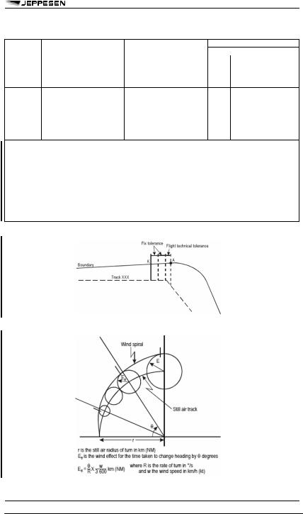
3.3.2Turn area using wind spiral
3.3.2.1 In the wind spiral method, the area is based on a radius of turn calculated for a specific value of true airspeed (TAS) and bank angle.
3.3.2.2 The outer boundary of the turn area is constructed using a spiral derived from the radius of turn. The spiral results from applying wind effect to the ideal flight path. See Figure I-2-3-3.
Table I-2-3-1 Turn construction parameter summary
© JEPPESEN, 2002, 2009. ALL RIGHTS RESERVED.
3 JUL 09 |
AIR TRAFFIC CONTROL |
207 |
FLIGHT PROCEDURES (DOC 8168) - GENERAL PRINCIPLES
Table I-2-3-1 Turn construction parameter summary (continued)
Figure I-2-3-1. Start of construction of outer boundary
Figure I-2-3-3. Wind spiral
© JEPPESEN, 2002, 2009. ALL RIGHTS RESERVED.