

AIR TRAFFIC CONTROL
.pdf28 JAN 11 AIR TRAFFIC CONTROL |
603 |
EU-OPS 1 AERODROME OPERATING MINIMUMS (AOM)
and to see and avoid obstacles in the take-off area. Such aircraft may be operated to take-off minimums shown in Table 3.
The take-off minimums established by an operator must be based upon the height from which the one engine inoperative net take-off flight path can be constructed. The RVR/VIS minimums used may not be lower than either those specified in Table 2 or 3.
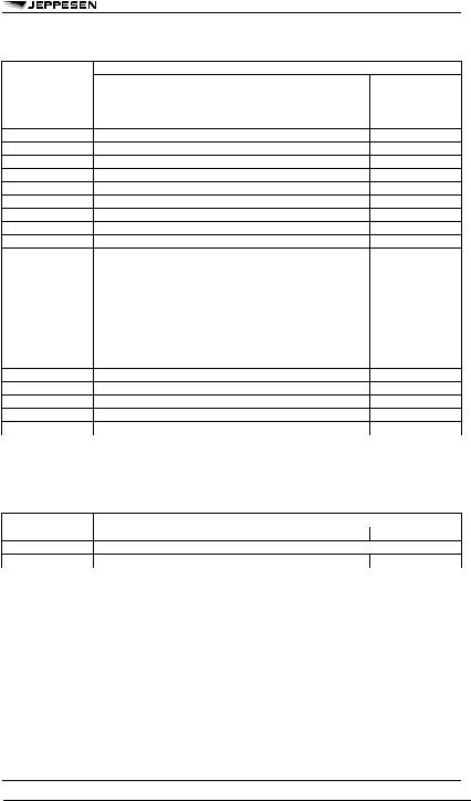
Table 2 TAKE-OFF RVR/VIS
1 For RVR/VIS below 400m Low Visibility Procedure must be in use.
2 The reported RVR/VIS of the initial part of take-off run can be replaced by pilot assessment. 3 For additional information about Approved Operators refer to the description below this table.
4 The required RVR value must be achieved for all relevant RVR reporting points except the initial part of take-off run. 5 For night operations at least RL and runway end lights are required.
Approved Operators:
a.Subject to the approval of the Authority and provided the requirements in paragraphs 1. to 5. below have been met, an operator may reduce the take-off minimum to 125m/150m when:
1.Low Visibility Procedures are in force,
2.High intensity CL spaced 15m or less and HIRL spaced 60m or less are in operation,
3.Crews have satisfactorily completed training in a simulator approved for this procedure,
4.A 90m visual segment is available from the cockpit at the start of the take-off run,
5.The required RVR value has been achieved for all of the relevant RVR reporting points.
b.Subject to approval of the Authority, an operator of an aircraft using an approved lateral guidance system or an approved HUD/HUDLS for take-off may reduce the take-off minimum to not lower than RVR 75m provided runway protection and facilities equivalent to Category III landing operations are available.
Table 3 ASSUMED ENGINE FAILURE HEIGHT ABOVE THE RUNWAY VERSUS RVR/VIS
1 The reported RVR/VIS of the initial part of the take-off run can be replaced by pilot assessment. 2 1500m is also applicable if no positive take-off flight path can be constructed.
When reported RVR/VIS is not available, the commander shall not commence take-off unless he can determine that the actual conditions satisfy the applicable take-off minimum.
7CIRCLE-TO-LAND MINIMUMS (EU-OPS 1)
An operator must ensure that the MDH is not below:
–the State published circling OCA(H),
–the MDH from Table 4,
–the MDH of the preceding instrument approach procedure.
An operator must ensure that the visibility is not below:
–the State published circling VIS,
–the VIS from Table 4,
–the RVR/CMV of the preceding instrument approach procedure.
© JEPPESEN, 1998, 2011. ALL RIGHTS RESERVED.

604 AIR TRAFFIC CONTROL 28 JAN 11
EU-OPS 1 AERODROME OPERATING MINIMUMS (AOM)
Table 4 MDH/METEOROLOGICAL VIS FOR CIRCLING APPROACHES
Circle-to-land with prescribed flight tracks is an accepted procedure within the meaning of this paragraph.
For night operations or for any operation where credit for runway and approach lights is required, the lights must be on and serviceable.
8DETERMINATION OF RVR/CMV FOR CAT I PRECISION, APV AND NON-PRECISION APPROACHES (EU-OPS 1)
APPROACH LIGHT SYSTEMS
The visual aids comprise standard runway day markings, approach and runway lighting (runway edge lights, threshold lights, runway end lights and in some cases also touch-down zone lights and/or runway centerline lights).
Table 5 APPROACH LIGHT SYSTEMS
RVR/CMV
The minimum RVR/CMV shall be the highest of the values derived from Table 6 and the minimum values for the specific approach type but not greater than the maximum values for the specific type of approach.
The values in Table 6 are derived from the following formula:
Required RVR/VIS(m) = [(DH or MDH(ft) x 0.3048)/ tan α] – length of approach lights (m)
The formula can also be used when calculating RVR values for steeper approaches angles (α) with the approval of the authority.
Table 6 RVR/CMV (m) vs DH/MDH and Lights – All Aircraft Categories
© JEPPESEN, 1998, 2011. ALL RIGHTS RESERVED.
16 APR 10 AIR TRAFFIC CONTROL |
605 |
EU-OPS 1 AERODROME OPERATING MINIMUMS (AOM)
Table 6 RVR/CMV (m) vs DH/MDH and Lights – All Aircraft Categories (continued)
8.1CAT I PRECISION (ILS, MLS, GLS, PAR) and APV
The minimum and maximum RVR/CMV values are as shown in Table 7.
Table 7 RVR/CMV (MIN/MAX)
The following requirements must be fulfilled:
–descent angle not above 4.5° for CAT A & B and not above 3.77° for CAT C & D, unless other approach angles are approved by the authority,
–final offset not more than 15° for CAT A & B and not more than 5° for CAT C & D.
An RVR of less than 750m may only be used:
–for CAT I approach operations to runways with FALS, TDZ and CL and with DH of 200ft,
–for CAT I approach operations to runways without TDZ and/or CL, when using an approved HUDLS or an equivalent approved system, or when conducting a coupled or a flight-director-flown approach to a DH not less than 200ft,
–for APV operations to runways with FALS, TDZ and CL, when using an approved HUD, but not below 600m.
The operator must ensure that the decision height to be used is not lower than:
–the minimum height to which the approach aid can be used without the required visual reference.
–the OCH for the aircraft category,
–the published decision height,
–200ft for CAT I approach operations,
–250ft for APV operation,
–the lowest decision height specified in the Aircraft Flight Manual or equivalent documents
whichever is higher.
© JEPPESEN, 1998, 2010. ALL RIGHTS RESERVED.

606 AIR TRAFFIC CONTROL 16 APR 10
EU-OPS 1 AERODROME OPERATING MINIMUMS (AOM)
8.2NON-PRECISION APPROACHES
All non-precision approaches shall be flown using the continuous descent final approach technique (CDFA) unless otherwise approved by the authority for a particular approach to a particular runway.
The missed approach, after an approach has been flown using CDFA technique, shall be executed when reaching the decision altitude (height) or the MAP, whichever occurs first. The lateral part of the missed approach procedure must be flown via the MAP unless otherwise stated in the procedure.
The RVR is the higher value of Table 6 (based on DH/MDH) and 8 depending on fulfilling the following requirements, but not above the maximum values from Table 8:
a.approach is flown using CDFA technique,
b.descent angle not above 4.5° for CAT A & B and not above 3.77° for CAT C & D, unless other approach angles are approved by the authority,
c.final offset not more than 15° for CAT A & B and not more than 5° for CAT C & D,
d.final approach segment of at least 3nm,
e.FAF or appropriate fix where descent is initiated is available, or distance to threshold is available by FMS, RNAV or DME,
f.if MAP is defined by timing, the distance from FAF to threshold is less than 8nm.
Table 8 RVR/CMV (MIN/MAX) – FULFILLING ALL REQUIREMENTS
If at least one of the requirements (a) to (f) above is not matched or the DH/MDH is more than 1200ft, the RVR is the higher value of Table 6 (based on DH/MDH) and 9, but not above the maximum values
from Table 9. For non-CDFA approaches the values from Table 6 have to be increased by 200m for CAT A & B and 400m for CAT C & D.
Table 9 RVR/CMV (MIN/MAX) – NOT FULFILLING ALL REQUIREMENTS
The operator must ensure that the minimum descent height or decision height to be used is not lower than:
–the minimum height to which the approach aid can be used (Table 10),
–the OCH for the aircraft category,
–the published minimum descent height/decision height,
–the lowest minimum descent height/decision height specified in the Aircraft Flight Manual or equivalent documents
whichever is higher.
Table 10 LOWEST MDH/DH NON-PRECISION APPROACHES
VISUAL REFERENCE
The pilot shall not continue an approach below minimum descent height unless at least one of the following elements is distinctly visible and identifiable to the pilot:
–elements of the approach light system,
–threshold, threshold markings, threshold lights or threshold identification lights,
–visual glide slope indicator,
–touchdown zone or touchdown zone markings,
–TDZ,
–RL,
–other visual references accepted by the authority.
9LOWER THAN STANDARD CAT I OPERATIONS (EU-OPS 1)
DECISION HEIGHT
A decision height for Lower Than Standard CAT I operations must not be lower than:
–the DH specified in the Aircraft Flight Manual or equivalent documents,
© JEPPESEN, 1998, 2010. ALL RIGHTS RESERVED.

16 APR 10 AIR TRAFFIC CONTROL |
607 |
EU-OPS 1 AERODROME OPERATING MINIMUMS (AOM)
–the minimum height to which the precision approach aid can be used without the required visual reference,
–the OCH for the aircraft category,
–the decision height the flight crew is authorized to operate,
–200ft
whichever is higher.
RVR/CMV
The lowest RVR values to be used by an operator for Lower Than Standard CAT I operations are shown in Table 11 below.
Table 11 RVR/CMV LOWER THAN STANDARD CAT I OPERATIONS
1 For operations to a minimum RVR of 450m Class I/T/1 ILS required. 2 For operations with RVR less than 450m Class II/D/2 ILS required. 3 For operations with RVR below 450m TDZ and/or CL required.
VISUAL REFERENCE
The pilot shall not continue an approach below decision height unless visual reference containing one of the following elements is attained and can be maintained:
–at least 3 consecutive lights being the centerline of the approach lights,
–TDZ, CL or RL,
–or a combination of the above.
The visual reference must include a lateral element of the ground pattern (like an approach lighting crossbar, landing threshold, a barrette of the TDZ) unless the operation is conducted utilizing an approved HUDLS to at least 150ft above threshold.
TYPE OF FACILITY
An ILS/MLS which supports Lower Than Standard CAT I operations must be an unrestricted facility with a straight-in course equal to or less than 3° offset and the ILS must be certificated to:
–Class I/T/1 for operations to a minimum RVR of 450m,
–Class II/D/2 for operations to less than 450m RVR.
Single ILS facilities are only acceptable if Level 2 performance is provided.
APPROVAL
To conduct Lower Than Standard CAT I operations:
–The operator shall be approved by the authority.
–The approach shall be flown auto-coupled to an autoland or an approved HUDLS shall be used to at least 150ft above threshold.
–The aircraft shall be certified in accordance to CS-AWO to conduct CAT II operations.
–The autoland system shall be approved for CAT IIIA operations.
–In service proving requirements shall be completed (aircraft, aerodrome, runway).
–Training shall be completed (low visibility operations – training & qualification applicable to CAT II operations as of Appendix 1 to OPS 1.450).
–The operator must ensure that Low Visibility Procedures are established and in operation at the landing aerodrome.
Due to the requirements above Jeppesen will publish minimums for Lower Than Standard CAT I operations on operator’s request on tailored charts.
10STANDARD CAT II OPERATIONS (EU-OPS 1)
DECISION HEIGHT
An operator must ensure that the decision height is not lower than:
–The minimum decision height specified in the Aircraft Flight Manual or equivalent documents,
–the minimum height to which the precision approach aid can be used without the required visual reference,
–the OCH for the aircraft category,
–the decision height to which the flight crew is authorized to operate,
–100ft,
whichever is higher.
RVR
The lowest minimums to be used by an operator for CAT II operations are shown in Table 12 below.
© JEPPESEN, 1998, 2010. ALL RIGHTS RESERVED.

608 AIR TRAFFIC CONTROL 16 APR 10
EU-OPS 1 AERODROME OPERATING MINIMUMS (AOM)
Table 12 RVR STANDARD CAT II OPERATIONS
1Auto-coupled or Approved HUDLS to below DH – which means continued use of the automatic flight control system or the HUDLS down to a height of 80% of the DH.
2Auto-coupled or Approved HUDLS to below DH – which means continued use of the automatic flight control system or the HUDLS down to a height of 80% of the DH.
3 RVR 300m may be used for aircraft conducting an autoland.
VISUAL REFERENCE
The pilot shall not continue an approach below decision height unless visual reference containing one of the following elements is attained and can be maintained:
–at least 3 consecutive lights being the centerline of the approach lights,
–TDZ, CL or RL,
–or a combination of the above.
The visual reference must include a lateral element of the ground pattern (like an approach lighting crossbar, landing threshold, a barrette of the TDZ) unless the operation is conducted utilizing an approved HUDLS to touchdown.
–the minimum decision height specified in the Aircraft Flight Manual or equivalent documents,
–the minimum height to which the precision approach aid can be used without the required visual reference,
–the OCH for the aircraft category,
–the decision height to which the flight crew is authorized to operate,
–100ft,
whichever is higher.
RVR
The lowest minimums depend on DH and available approach light system as shown in Table 13 below.
11OTHER THAN STANDARD CAT II OPERATIONS (EU-OPS 1)
DECISION HEIGHT
An operator must ensure that the decision height is not lower than:
Table 13 RVR OTHER THAN STANDARD CAT II OPERATIONS
1 For operations to a minimum RVR of 450m Class I/T/1 ILS required. 2 For operations with RVR less than 450m Class II/D/2 ILS required. 3 Autoland or approved HUDLS utilized to touchdown.
4 For operations in RVR of 400m or less CL must be available. 5 For operations in RVR of 400m or less CL must be available. 6 For operations in RVR of 400m or less CL must be available.
To conduct Other Than Standard CAT II operations the operator must ensure that appropriate low visibility procedures are established and in operation at the landing aerodrome.
VISUAL REFERENCE
The pilot shall not continue an approach below decision height unless visual reference containing one of the following elements is attained and can be maintained:
–at least 3 consecutive lights being the centerline of the approach lights,
–TDZ, CL or RL,
– or a combination of the above.
The visual reference must include a lateral element of the ground pattern (i.e. an approach lighting crossbar, landing threshold, a barrette of the TDZ) unless the operation is conducted utilizing an approved HUDLS to touchdown.
TYPE OF FACILITY
An ILS/MLS which supports Other Than Standard CAT II operations shall be an unrestricted facility with a straight-in course equal to or less than 3° offset and the ILS shall be certificated to:
© JEPPESEN, 1998, 2010. ALL RIGHTS RESERVED.

16 APR 10 AIR TRAFFIC CONTROL |
609 |
EU-OPS 1 AERODROME OPERATING MINIMUMS (AOM)
–Class I/T/1 for operations to a minimum RVR of 450m and to a DH of 200ft or more,
–Class II/D/2 for operations in RVR of less than 450m or to a DH of less than 200ft.
Single ILS facilities are only acceptable if Level 2 performance is provided.
Jeppesen will publish minimums for Other Than Standard CAT II operations only if the procedure is approved for their use by the State of the aerodrome.
12 CAT III OPERATIONS (EU-OPS 1)
CAT III operations are subdivided as follows:
a.CAT IIIA: decision height lower than 100ft and RVR not less than 200m,
b.CAT IIIB: decision height lower than 100ft or no decision height and RVR less than 200m but not less than 75m.
DECISION HEIGHT
For operations in which a decision height is used, an operator must ensure that the decision height is not lower than:
–the minimum decision height specified in the Aircraft Flight Manual or equivalent documents,
–the minimum height to which the precision approach aid can be used without the required visual reference,
–the decision height to which the flight crew is authorized to operate.
Operations with no decision height may only be conducted if:
–the operation with no decision height is authorized in the Aircraft Flight Manual,
–the approach aid and aerodrome facilities can support such operations,
–the operator has an approval for CAT III operations with no decision height.
NOTE: In the case of a CAT III runway it may be assumed that operations with no decision height can be supported unless specifically restricted as published in the AIP or by NOTAM.
RVR
The lowest minimums to be used by an operator for CAT III operations are shown in Table 14.
Table 14 CAT III OPERATIONS
1 Flight control system redundancy is determined under CS-AWO by the minimum certificated decision height. 2 For aircraft certificated in accordance with CS-AWO 321 (b)(3) or equivalent.
3 The fail-operational system referred to may consist of a fail-operational hybrid system.
VISUAL REFERENCE
For CAT IIIA and for CAT IIIB operations either with fail-passive flight control systems or with the use of an approved HUDLS, a pilot may not continue an approach below the decision height unless a visual reference of one of the following elements is attained and can be maintained:
–at least 3 consecutive lights being the centerline of the approach lights,
–TDZ, CL or RL,
–or a combination of the above.
For CAT IIIB operations conducted either with fail-operational flight control systems or with a fail-operational hybrid landing system (comprising e.g. a HUDLS) using a decision height a pilot may not continue an approach below the decision height unless a visual reference containing at least one centerline light is attained and can be maintained.
13 FAILED OR DOWNGRADED
EQUIPMENT (EU-OPS 1)
The effect on landing minimums is shown in Table 15 below.
Table 15 FAILED OR DOWNGRADED EQUIPMENT – EFFECT ON LANDING MINIMUMS Failed or Downgraded
© JEPPESEN, 1998, 2010. ALL RIGHTS RESERVED.

610 AIR TRAFFIC CONTROL 16 APR 10
EU-OPS 1 AERODROME OPERATING MINIMUMS (AOM)
Table 15 FAILED OR DOWNGRADED EQUIPMENT – EFFECT ON LANDING MINIMUMS (continued) Failed or Downgraded
1 Other than Standard CAT II: No effect.
2 Other than Standard CAT II: No effect.
3 Other than Standard CAT II: No effect.
NOTE 1: Applicable conditions for the use of the table above:
–Multiple failures of runway lights are not acceptable.
–Deficiencies of approach and runway lights are treated separately.
–CAT II/III operations: A combination of deficiencies in runway lights and RVR assessment equipment is not allowed.
–Failures other than ILS affect RVR only and not DH .
NOTE 2: For CAT IIIB operations with no decision height, an operator shall ensure that, for aircraft authorized to conduct no decision height operations with the lowest RVR limitations, the following applies in addition to the table above:
–RVR: At least one RVR value must be available at the aerodrome.
–Runway lights:
a.No RL or no CL: Day - RVR 200m.
b.No RL or no CL: Night - Not allowed.
c.No TDZ lights – No restriction.
d.No Stand-by power to RL: Day – RVR 200m.
e.No Stand-by power to RL: Night – Not allowed.
14ENHANCED VISION SYSTEMS (EU-OPS 1)
The Enhanced Vision System (EVS) may only be used for ILS, MLS, PAR, GLS and APV operations with a DH not lower than 200ft or on approaches when using approved vertical flight path guidance to a MDH or DH not below 250ft.
A pilot using an EVS certificated for the purpose of this paragraph and used in accordance with the procedures and limitations of the approved flight manual, may:
a.Continue an approach below DH or MDH to 100ft above threshold elevation provided that at least one of the following visual references is displayed and identifiable on the enhanced vision system:
–elements of the approach lighting or
–runway threshold, identified by the beginning of the runway landing surface, threshold lights or by threshold identification lights and
–touchdown zone identified by touchdown zone landing surface, touchdown zone lights, touchdown zone markings or by runway lights.
b.Reduce the calculated RVR/CMV for the approach according the Table 16 below.
© JEPPESEN, 1998, 2010. ALL RIGHTS RESERVED.

16 APR 10 AIR TRAFFIC CONTROL |
611 |
EU-OPS 1 AERODROME OPERATING MINIMUMS (AOM)
Table 16 RVR/CMV REDUCTION WHEN USING EVS
A pilot may not continue an approach below 100ft above threshold elevation, unless one of the following visual references is distinctly visible and identifiable to the pilot without reliance on the enhanced vision system:
–The lights or markings of the threshold,
–The lights or markings of the touchdown zone.
15SINGLE PILOT OPERATIONS (EU-OPS 1)
For single pilot operations the operator must calculate the minimum RVR/VIS for all approaches as stated above with the exceptions shown below.
a.An RVR of less than 800m may be used for CAT I approaches provided any of the following is used at least down to the applicable DH:
–A suitable autopilot, coupled to an ILS or MLS, which is not promulgated as restricted,
–An approved HUDLS (including EVS where appropriate) or equivalent approved system,
b.The minimum RVR/CMV shall not be less than 600m where TDZ and/or CL are not available.
c.An RVR of less than 800m may be used for APV operations to runways with FALS, TDZ and CL when using an approved HUDLS, an equivalent approved system or when conducting a coupled approach to a DH equal to or greater than 250ft.
Jeppesen will publish minimums for single pilot operations only on operator’s request on tailored charts.
16 PLANNING MINIMUMS (EU-OPS 1)
An operator shall only select an aerodrome as a take-off alternate aerodrome when appropriate weather reports or forecasts or any combination thereof indicate, that during a period commencing one hour before and ending one hour after the estimated time of arrival, the weather conditions will be at or above the applicable landing minimum. The ceiling must be taken into account when only non-precision or circling approaches are available. Any limitation related to one-engine-inoperative operations must be taken into account.
An operator shall only select the destination aerodrome when appropriate weather reports or forecasts or any combination thereof indicate, that during a period commencing one hour before and ending one hour after the estimated time of arrival, the weather conditions will be at or above the applicable landing minimum as follows:
–RVR/VIS,
–ceiling at or above MDH for non-precision or circling approaches,
or two destination alternate aerodromes are selected if the weather conditions are below the applicable planning minimums.
An operator shall only select an aerodrome as:
© JEPPESEN, 1998, 2010. ALL RIGHTS RESERVED.

612 AIR TRAFFIC CONTROL 16 APR 10
EU-OPS 1 AERODROME OPERATING MINIMUMS (AOM)
–destination alternate aerodrome,
–isolated aerodrome,
–enroute alternate aerodrome (ERA),
–3% ERA (an ERA selected for the purpose of reducing contingency fuel to 3%)
when appropriate weather reports or forecasts or any combination thereof indicate, that during a period commencing one hour before and ending one hour after the estimated time of arrival, the weather conditions will be at or above the planning minimums as in Table 17 below.
Table 17 PLANNING MINIMUMS
Note 1: RVR
Note 2: The ceiling must be at or above the MDH
An operator shall not select an aerodrome as an ETOPS enroute alternate aerodrome when appropriate weather reports or forecasts or any combination thereof indicate, that between the anticipated time of landing until one hour after the latest possible time of landing, conditions calculated by adding the addi-
tional limits of Table 18 below will exist. An operator shall include in the Operations Manual the method for determining the operating minima at the planned ETOPS enroute alternate aerodrome.
Jeppesen will publish planning minimums on request only.
Table 18 PLANNING MINIMUMS – ETOPS
17 COMMENCEMENT AND CONTINUATION OF AN APPROACH - APPROACH BAN (EU-OPS 1)
An instrument approach may be commenced regardless of the reported RVR/VIS but the approach shall not be continued beyond the outer marker or equivalent position, if the reported RVR/VIS is less than the applicable minima. Where RVR is not available, RVR values may be derived by converting the reported visibility. If, after passing the outer marker or equivalent position the reported RVR/VIS falls below the applicable minimum, the approach may be continued to DA(H) or MDA(H).
Where no outer marker or equivalent position exist, the pilot shall make the decision to continue or abandon the approach before descending below 1000ft above the aerodrome on the final approach segment. If the MDA(H) is 1000ft or more about aerodrome the operator shall establish a height for each approach procedure, below which the approach shall not be continued if RVR/VIS is less than the applicable minimum.
The approach may be continued below DA(H) or MDA(H) and the landing may be completed provided that the required visual reference is established at the DA(H) or MDA(H) and is maintained.
The touchdown zone RVR is always controlling. If reported and relevant, the mid-point and stop-end RVR are also controlling. The minimum RVR for the mid-point is 125m or the RVR required for the touchdown zone if less. The minimum RVR for the stop-end is 75m. For aircraft equipped with a roll-out guidance or control system, the minimum RVR value for the mid-point is 75m.
Relevant in this context means that part of the runway used during the high speed phase of the landing down to a speed of approximately 60kt.
18JAR-OPS 1 AOM (EU-OPS 1 Subpart E – Appendix 1 to OPS 1.430 old)
18.1GENERAL
The following explanation is an excerpt based on EU-OPS 1 (Subpart E – Appendix 1 to OPS 1.430 old) which is the same as the former JAR-OPS 1 regarding the use and method used to determine AOM. The lighting requirements are the same as described in the EU-OPS section.
This paragraph focuses on the differences, applicable to JAR-OPS 1 operators.
The following table identifies the relevant paragraphs for JAR-OPS 1 operators.
© JEPPESEN, 1998, 2010. ALL RIGHTS RESERVED.