

AIR TRAFFIC CONTROL
.pdf5 JUN 09 |
AIR TRAFFIC CONTROL |
263 |
FLIGHT PROCEDURES (DOC 8168) - ARRIVAL AND NON-PRECISION
APPROACH PROCEDURES
1AREA NAVIGATION (RNAV) ARRIVAL AND APPROACH PROCEDURES FOR NAVIGATION SYSTEMS USING BASIC GNSS RECEIVERS
1.2.3Navigation database
Departure and approach waypoint information is contained in a navigation database. If the navigation database does not contain the departure or approach procedure, then the basic GNSS stand-alone receiver or FMC shall not be used for these procedures.
1.4GNSS APPROACH PROCEDURES
1.4.1 Usually, flying a basic GNSS non-preci- sion instrument approach procedure is very similar to a traditional approach. The differences include the navigation information displayed on the GNSS equipment control and display unit and the terminology used to describe some of the features.
1.4.7 Approaches must be flown in accordance with the aircraft operating manual and the procedure depicted on an appropriate instrument approach chart.
1.4.9Procedures must be established in the event that GNSS outages occur. In these situations, the operator must rely on other instrument procedures. For installations where the FMC includes an AAIM capability, there may be no disruption to the operation unless the outage exceeds the FMC capability to sustain the required level of performance.
1.4.10To begin the basic GNSS approach, the appropriate airport, runway/approach procedure and initial approach fix (IAF) must first be selected. Pilots must maintain situational awareness to determine the bearing and distance to the GNSS procedure IAF before flying the procedure. This can be critical to ascertain whether entering a right or left base when entering the terminal approach area in the vicinity of the extended runway centre line. All sectors and step-
1.4.2Flying a basic GNSS approach is nordowns are based on the bearing and distance to the
mally point-to-point navigation and independent of any ground-based navaids.
1.4.3 GNSS procedures utilize a straight line (TO-TO) flight from waypoint to waypoint, as sequenced in the database. Slight differences between the published track and track presented may occur. These differences are usually due to rounding of the track bearing and/or the application of magnetic variation.
1.4.4 The approach cannot be flown unless that instrument approach is retrievable from the avionics database which:
a.contains all the waypoints depicted in the approach to be flown;
b.presents them in the same sequence as the published procedure chart; and
c.is updated for the current AIRAC cycle.
1.4.5To ensure the correctness of the GNSS database display, pilots should check the data displayed as reasonable for the GNSS approach after loading the procedure into the active flight plan and prior to flying the procedure. Some GNSS avionics implementations provide a moving map display which aids the pilot in conducting this reasonableness check.
1.4.6Pilots should no attempt to fly any
approach unless the procedure is contained in the current navigation database. Flying from one approach waypoint to another waypoint that has not been loaded from a database does not ensure compliance with the published approach procedure. For the basic GNSS receiver, the proper RAIM alert limit will not be selected and the CDI sensitivity will not automatically change to ±0.6 km (0.3 NM). An FMC using GNSS may contain either the same RAIM alert limits as the basic GNSS receiver, or appropriate navigation performance indications and alerts for ±0.6 km (0.3 NM ). For both basic GNSS and FMCs, manually setting CDI sensitivity does not automatically change the RAIM alert limit on some avionics implementations.
IAF for that area, which the aircraft should be proceeding direct to, unless on radar vectors.
1.4.11 Pilots must fly the full approach from the IAF unless specifically cleared otherwise. Randomly joining an approach at an intermediate fix does not ensure terrain clearance.
1.4.13The pilot must be aware of the bank angle/ turn rate that the particular GNSS avionics implementation uses to compute turn anticipation, and whether wind and airspeed are included in the calculations. This information must be in the manual describing avionics functionality. Overor under-banking the turn onto the final approach course may significantly delay achieving course alignment and may result in high descent rates to achieve the next segment altitude.
1.4.14Pilots must pay particular attention to the exact operation of the basic GNSS avionics implementations for performing holding patterns and, in the case of overlay approaches, operations such as procedure turns and course reversals. These procedures may require manual intervention by the pilot to stop the sequencing of waypoints by the receiver and to resume automatic GNSS navigation sequencing once the manoeuvre is complete. The same waypoint may appear in the route of flight more than one consecutively (IAF, FAF, MAHF on a procedure turn/course reversal).
1.4.19 All FMCs and some stand-alone basic GNSS receivers provide altitude information. However, the pilot must still comply with the published minimum altitudes using the barometric altimeter. Where the FMC provides vertical information, flight director guidance cues, or coupled autopilot operation, the pilot should follow the appropriate information or cues along with any necessary cross checks with the barometric altimetry.
© JEPPESEN, 2002, 2009. ALL RIGHTS RESERVED.

264 AIR TRAFFIC CONTROL 5 JUN 09
FLIGHT PROCEDURES (DOC 8168) - ARRIVAL AND NON-PRECISION
APPROACH PROCEDURES
1.5INITIAL APPROACH SEGMENT
1.5.1Offset IAFs
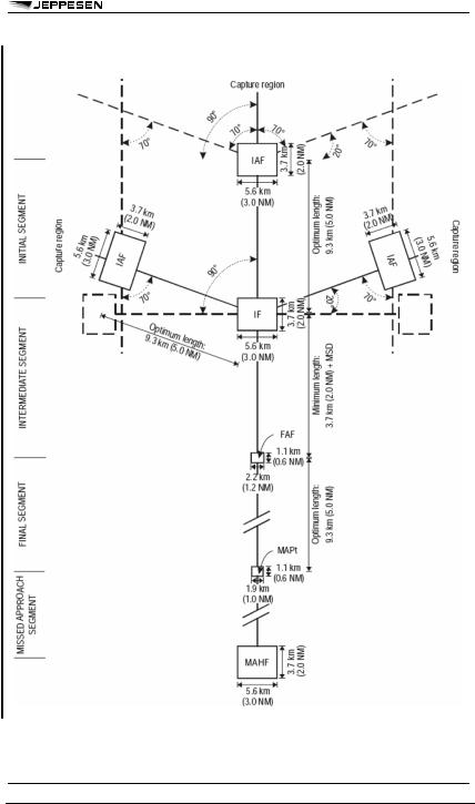
1.5.1.1Offset IAFs in procedures based on the “Y” or “T” bar design concept for basic GNSS are aligned such that a course change of 70° to 90° is required at the IF. A capture region is associated with each IAF of the basic GNSS procedure from which the aircraft will enter the procedure. The capture region for tracks inbound to the offsets IAFs extends 180° about the IAFs, thus providing a Sector 3 entry in cases where the track change at the IF is 70°. The central IAF is aligned with the final approach track, the angle being identical to the track change at the IF for the corresponding offset IAF. In this way, there are no gaps between the capture regions of all IAFs regardless of the course change at the IF. Its capture region is 70° to 90° either side of the final track. For turns greater than 110° at the IAFs, Sector 1 or 2 entries should be used.
1.5.1.2When used, the central initial approach segment has no maximum length. The optimum length is 9.3 km (5.0 NM). The minimum segment length is established by using the highest initial approach speed of the fastest category of aircraft for which the approach is designed and the minimum distance between waypoints required by the aircraft avionics in order to correctly sequence the waypoints.
1.6INTERMEDIATE APPROACH SEGMENT
1.6.1 The intermediate segment consists of two components — a turning component abeam the IF followed by a straight component immediately before the final approach fix (FAF). The length of the straight component is variable but will not be less than 3.7 km (2.0 NM) allowing the aircraft to be stabilized prior to overflying the FAF.
1.7FINAL APPROACH SEGMENT
1.7.1 The final approach segment for a GNSS approach will begin at a named waypoint normally located 9.3 km (5.0 NM) form the runway threshold.
1.7.3Stepdown fixes
1.7.3.1A stepdown fix is flown in the same manner as a ground-based approach. Any required stepdown fixes prior to the missed approach waypoint will be identified by along-track distances.
1.7.3.2Where the FMC includes a vertical navigation capability, the navigation database procedure may contain a continuous descent flight path that remains above the stepdown procedure vertical profile. Use of FMC vertical navigation capability will be subject to flight crew familiarity, training and any other requirements of the operational approval.
1.7.4Descent gradient/angle
The optimum descent gradient/angle is 5.2 per cent/ 3°, however, where a higher gradient/angle is necessary, the maximum permissible is 6.5 per cent/3.7°. The descent gradient/angle is published.
1.8MISSED APPROACH SEGMENT
1.8.1CDI Sensitivity
1.8.1.1 For basic GNSS receivers, sequencing of the guidance past the MAPt activitates transition of the CDI sensitivity and RAIM alert limit to terminal mode (1.9 km (1.0 NM)).
© JEPPESEN, 2002, 2009. ALL RIGHTS RESERVED.
5 JUN 09 |
AIR TRAFFIC CONTROL |
265 |
FLIGHT PROCEDURES (DOC 8168) - ARRIVAL AND NON-PRECISION
APPROACH PROCEDURES
Figure II-3-1-1. Basic GNSS RNAV approach
© JEPPESEN, 2002, 2009. ALL RIGHTS RESERVED.

266 |
AIR TRAFFIC CONTROL 5 JUN 09 |
||
|
FLIGHT PROCEDURES (DOC 8168) - ARRIVAL AND NON-PRECISION |
||
|
APPROACH PROCEDURES |
||
|
3 |
AREA NAVIGATION (RNAV) |
|
|
|
ARRIVAL AND APPROACH |
|
|
|
PROCEDURES BASED ON |
|
|
|
VOR/DME |
|
|
3.1 Area navigation (RNAV) approach proce- |
||
|
dures based on VOR/DME are assumed to be based |
||
|
on one reference facility composed of a VOR and |
||
|
collocated DME equipment. The reference facility will |
||
|
be indicated. |
||
|
3.2 The VOR/DME RNAV approach procedure is |
||
|
a non-precision approach procedure. |
||
|
3.6 |
|
NAVIGATION ACCURACY FACTORS |
|
3.6.1 |
The factors on which the navigation accu- |
|
|
racy of the VOR/DME RNAV depends are: |
||
a. ground system tolerance;
b. airborne receiving system tolerance; c. flight technical tolerance;
d. system computation tolerance; and e. distance from the reference facility.
3.6.2 The fixes used in the procedure are indicated as waypoints. These waypoints are referred to by alphanumeric indicators. Their positions are specified in latitude and longitude (degrees, minutes and seconds with an accuracy to the nearest second of arc or equivalent). A radial and DME distance (to an accuracy of 0.18 km (0.1 NM)) from the reference facility are also provided.
3.7 ARRIVAL SEGMENT
Standard instrument arrivals (STARs) can be based on RNP criteria (limited to RNP 1 or better) or on specific RNAV criteria. When specific criteria are used, the same principles apply to the protection of all of the arrival phase. The FTT, however, is assumed to be equal to:
a. 3.7 km (2.0 NM) until at 46 km (25 NM) from the IAF; and
b. 1.9 km (1.0 NM) after this point.
3.8 INITIAL APPROACH SEGMENT
When the procedure requires a track reversal, a racetrack pattern may be established.
3.9 FINAL APPROACH SEGMENT
3.9.1 The final approach segment is generally aligned with the runway.
3.9.2 The minimum obstacle clearance in the primary area of the final approach segment is 75 m (246 ft).
3.9.3 Waypoints in the final approach
3.9.3.1 The FAF is defined by a fly-by waypoint.
3.9.3.2 A flyover waypoint is also provided at the runway threshold.
© JEPPESEN, 2002, 2009. ALL RIGHTS RESERVED.

5 JUN 09 |
AIR TRAFFIC CONTROL |
267 |
FLIGHT PROCEDURES (DOC 8168) - ARRIVAL AND NON-PRECISION
APPROACH PROCEDURES
3.10MISSED APPROACH SEGMENT
3.10.1The missed approach waypoint (MAPt) is defined by a flyover waypoint. From the earliest MAPt, the area splays at 15° on each side of the missed approach track, at least until the SOC is reached. This allows for the limitations of some RNAV systems, and the pilot’s workload at the beginning of the missed approach phase.
3.10.2A missed approach holding fix (MAHF) defines the end of the missed approach segment. It is located at or after the point where the aircraft, climbing at the minimum prescribed gradient, reaches the minimum altitude for enroute or holding, whichever is appropriate.
5AREA NAVIGATION (RNAV) ARRIVAL AND APPROACH
PROCEDURES BASED ON GBAS
No arrival criteria specifically designed for GBAS exist. Arrival operations based upon basic GNSS or SBAS may be flown by aircraft with a navigation system that is compatible with the optional GBAS positioning service. Such operations may not be flown using a navigation system meeting only the minimum GBAS avionics requirements, unless it is also equipped with basic GNSS or SBAS avionics as appropriate.
© JEPPESEN, 2002, 2009. ALL RIGHTS RESERVED.

5 JUN 09 |
AIR TRAFFIC CONTROL |
269 |
FLIGHT PROCEDURES (DOC 8168) - APPROACH PROCEDURES
WITH VERTICAL GUIDANCE
1APV/BARO-VNAV APPROACH
PROCEDURES
NOTE: Barometric vertical navigation (baro-VNAV) is a navigation system that presents to the pilot computed vertical guidance referenced to a specified vertical path angle (VPA), normally 3°. The computerresolved vertical guidance is based on barometric altitude and is specified as a VPA from reference datum height (RDH).
1.1.1Procedure classification
1.1.1.1 The information in this section refers only to the procedures designed using APV/baro-VNAV criteria found in Volume II. Part III, Section 3, Chapter 4. APV/baro-VNAV approach procedures are classified as instrument approach procedures in support of approach and landing operations with vertical guidance. Such procedures are promulgated with a decision altitude/height (DA/H). They should not be confused with classical non-pre- cision approach (NPA) procedures, which specify a minimum descent altitude/height (MDA/H) below which the aircraft must not descend.
1.1.1.2APV/baro-VNAV procedures provide a greater margin of safety than non-precision approach procedures by providing for a guided, stabilized descent to landing. They are particularly relevant to large commercial jet transport aircraft, for which they are considered safer than the alternative technique of an early descent to minimum altitudes. An independent altimeter cross-check which is available for ILS, MLS, GLS, APV I/II or CAT I is not available with APV/baro-VNAV since the altimeter is also the source on which the vertical guidance is based. Mitigation of altimeter failures or incorrect settings shall be accomplished by means of standard operating procedures similar to those applied to non-precision approach procedures.
1.1.1.3However, the inaccuracies inherent in barometric altimeters, combined with the certificated performance of the specific area navigation (RNAV) mode used, make these procedures less accurate than precision approach systems. In particular, with certain systems the aircraft may not arrive within the Annex 14 obstacle-free surfaces, and the pilot should consider this possibility when making the decision to land at DA/H.
1.1.1.4The lateral portions of APV/baro-
VNAV criteria are based on RNAV non-preci- sion criteria. However, the FAF is not part of the APV/baro-VNAV procedure and is replaced by a final approach point, although the RNAV FAF may be used as a final approach course fix in database design. Similarly, the MAPt is replaced by an aircraft category dependent DA/H.
1.1.1.5 The APV/baro-VNAV minimum DH is 75 m (246 ft) plus a height loss margin. However, this minimum DH limit must be increased by the operator to at least 90 m (295 ft) plus a height loss margin when the lateral navigation system is not certificated to ensure the aircraft will arrive within the Annex 14 inner approach, inner transitional and balked land-
ing surfaces (extended as necessary above the inner horizontal surface to OCH) with a high degree of probability.
1.2.2Atmospheric effects
1.2.2.1Atmospheric errors associated with non-standard temperatures are considered in the design of the approach obstacle clearance surface. When temperatures are lower than standard, the aircraft’s true altitude will be lower than its barometric indicated altitudes.
1.2.2.2Most existing VNAV systems do not correct for non-standard temperatures. At temperatures below standard, these errors can be significant and increase in magnitude as altitude above the station increases. The gradient of the approach obstacle clearance surface is reduced as a function of the minimum temperature promulgated for the procedure.
1.2.3Along-track position uncertainty
All RNAV systems have some amount of along-track error. This along-track uncertainty can mean that the VNAV system will start the descent too early and result in an error in the vertical path. This is compensated for in procedure design by relocating the threshold level origin of the approach obstacle clearance surface.
1.2.4Flight technical error (FTE)
Flight technical error (FTE) is assumed to be contained within the standard non-precision margin of 75 m (246 ft). This is added below the VPA before the obstacle clearance surface is adjusted for cold temperature and along-track error.
1.2.5Other system errors
Other errors include static source error, non-homoge- nous weather phenomena and latency effects. These are insignificant compared with the other errors already addressed and are considered as contained within the existing margin.
1.2.6Blunder errors
Application of an incorrect or out-of-fate altimeter setting, either by air traffic control of the pilot, is possible and must be prevented by appropriate operational techniques.
1.3EQUIPMENT REQUIREMENTS
1.3.1 APV/baro-VNAV procedures are intended for use by aircraft equipped with flight management systems (FMS) or other RNAV systems capable of computing baro-VNAV paths and displaying the relevant deviations on the instrument display.
1.4OPERATIONAL CONSTRAINTS
1.4.1 Pilots are responsible for any necessary cold temperature corrections to all published minimum altitudes/heights. This includes:
a.the altitudes/heights for the initial and intermediate segment(s);
b.the DA/H; and
c.subsequent missed approach altitudes/heights.
© JEPPESEN, 2002, 2009. ALL RIGHTS RESERVED.

270 AIR TRAFFIC CONTROL 5 JUN 09
FLIGHT PROCEDURES (DOC 8168) - APPROACH PROCEDURES
WITH VERTICAL GUIDANCE
NOTE: The final approach path vertical angle (VPA) is safeguarded against the effects of low temperature by the design of the procedure.
1.4.2Temperatures below the promulgated minimum
Baro-VNAV procedures are not permitted when the aerodrome temperature is below the promulgated minimum aerodrome temperature for the procedure, unless the flight management system (FMS) is equipped with approved cold temperature compensation for the final approach. In this case, the minimum temperature can be disregarded provided it is within the minimum certificated temperature limits for the equipment. Below this temperature, and for aircraft that do not have FMS equipped with approved cold temperature compensation for the final approach, an LNAV procedure may still be used provided that:
a.a conventional RNAV non-precision procedure and APV/LNAV OCA/H are promulgated for the approach; and
b.the appropriate cold temperature altimeter correction is applied to all minimum promulgated altitudes/heights by the pilot.
1.4.3Vertical path angle (VPA) deviation table
1.4.3.1 A VPA deviation table provides an aerodrome temperature with an associated true vertical path angle. This table is intended to advise flight crews that, although the non-temperature-compen- sated aircraft’s avionics system may be indicating the promulgated final approach vertical path angle, the actual vertical path angle is different form the information presented to them by the aircraft avionics system. This table is not intended to have the pilot adjust the VPA flown to achieve the actual promulgated vertical path angle, nor is it meant to affect those avionics systems that have a capacity to properly apply temperature compensation to a baro-derived final approach VPA. Non-compensated baro-VNAV guidance should not be flown when the aerodrome temperature is below the lowest promulgated temperature.
1.4.4Altimeter setting
Baro-VNAV procedures shall only be flown with:
a.a current local altimeter setting source available; and
b.the QNH/QFE, as appropriate, set on the aircraft’s altimeter.
Procedures using a remote altimeter setting source cannot support a baro-VNAV approach.
1.4.5Vertical guidance sensitivity
1.4.5.1 The baro-VNAV vertical guidance display sensitivity varies with different equipment. However, cockpit displays showing vertical path deviation must be suitably located and have sufficient sensitivity to enable the pilot to limit vertical path excursions to less than:
a.+30 m (+100 ft); and
b.-15 m (-50 ft)
from the VPA.
1.4.5.2Vertical path deviation
Where equipment does not meet these criteria, an operational assessment and specific flight crew procedures may be required for the approval of baroVNAV operations. This may include requirements for the availability and use of a flight director or autopilot system.
1.4.6 The LNAV FAF and MAPt are used for coding purposes for the baro-VNAV procedure and are not intended to inhibit descent at the FAP or to restrict DA/H.
2AREA NAVIGATION (RNAV) ARRIVAL AND APPROACH PROCEDURES BASED ON SBAS
2.2SBAS PROCEDURE DESIGN CONSIDERATIONS
2.2.1 SBAS operations are based on the following design criteria:
a.LNAV: Basic GNSS criteria;
b.LNAV/VNAV: Baro-VNAV criteria; and
c.APV: Specific APV-I and II criteria.
Published temperature restrictions for barometric VNAV procedures do not apply to SBAS approach operations.
2.2.2 Publication and minima line description for APV. The charted minima lines associated with SBAS APV-I or APV-II performance levels are labeled “LPV” (localizer performance with vertical guidance). This labeling is consistent with existing SBAS avionics standard annunciations and indicates that the lateral performance is equivalent to an ILS localizer lateral performance.
2.3MISSED APPROACH WITH TURNING POINT PRIOR TO THRESHOLD
2.3.1 Normally, the MAPt is located at the LTP/FTP for NPA and when arriving at the DA for vertically guided approaches. To accommodate procedures requiring a missed approach turning point prior to the runway threshold, the MAPt can be located at the missed approach turning point. For a vertically guided procedure, the distance prior to threshold where the missed approach turning point is located is limited by the FTP crossing height (TCH value).
2.4.2Procedure identification. SBAS procedures are RNAV procedures and shall be identified as follows: RNAV (GNSS) RWY XX.
2.4.3Charting of SBAS minima lines. Minima lines associated with SBAS APV I/II performance as defined in Annex 10 are charted as LPV (localizer performance with vertical guidance).
2.4.4Charting of an SBAS channel number. SBAS APV procedures can be selected through the use of a channel number. This five-digit number is included in the final approach segment (FAS) data block in the procedure database and shall be charted. Alternatively, the procedure can be selected through the use of a menu-driven selection process.
© JEPPESEN, 2002, 2009. ALL RIGHTS RESERVED.

5 JUN 09 |
AIR TRAFFIC CONTROL |
271 |
FLIGHT PROCEDURES (DOC 8168) - APPROACH PROCEDURES
WITH VERTICAL GUIDANCE
2.4.5Charting of the SBAS approach ID. The FAS data block also includes an SBAS approach ID. This ID consists of four alphanumeric characters (e.g. S24A). This would imply an SBAS (S) procedure to runway 24 (24) and it is the first (A) SBAS procedure to this runway. Charting of the approach ID is the equivalent of charting the identity of a conventional navigation aid.
2.4.6Non-applicability of the charted temperature restriction for SBAS LNAV/VNAV procedures. Charted barometric VNAV temperature restrictions do not apply when vertical guidance is provided by SBAS.
2.4.7Reduced level of SBAS NOTAM service. A reduced level of SBAS NOTAM service can be provided at specific area edge locations without overburdening the NOTAM system. Since degradation of SBAS lateral service to HPL values greater than 556 meters is extremly unlikely, the reduced SBAS NOTAM service monitors SBAS lateral performance only at these locations.
2.4.8Promulgation of information concerning SBAS NOTAM service. The information that has to be promulgated to the pilot, is the identification of the level of SBAS NOTAM service that is provided in specific locations. The State is responsible to identify the level of SBAS NOTAM service that is available.
© JEPPESEN, 2002, 2009. ALL RIGHTS RESERVED.

4 MAR 11 AIR TRAFFIC CONTROL |
273 |
FLIGHT PROCEDURES (DOC 8168) - PRECISION APPROACH PROCEDURES
1GBAS PRECISION APPROACH PROCEDURES
1.1APPROACH CONDUCT
A precision approach using GBAS is selected by use of a channel number in the airborne equipment. The GBAS precision approach is carried out in a manner very similar to an ILS precision approach by using lateral guidance on the intermediate segment until intercepting the glide path, whereupon vertical guidance is initiated and continued, along with lateral guidance, for landing.
1.2GBAS APPROACH DISPLAY CRITERIA
1.2.1GBAS provides precision approach service equivalent to ILS Category I approach service. Minimum required GBAS display functionality is equivalent to ILS. GBAS continuously provides very accurate distance to landing threshold information. System failure display and annunciation are equivalent to ILS.
1.2.2The GBAS path is defined differently from an ILS path. Data defining the path, including the glide path, lateral sector width, lateral sensitivity and other characteristics of the guidance sector, are transmitted by ground equipment to the airborne system using a high-integrity digital data message. The digital message defines the final approach segment (FAS) path and guidance characteristics. The airborne system geometrically calculates the path and defines the guidance characteristics specified in the transmitted digital data. The airborne system generates guidance with characteristics similar to other precision approach systems such as ILS that transmit electronic beams for the aircraft equipment to track.
1.4PUBLICATION
The instrument approach chart for a GBAS approach procedure is identified by the title GLS RWY XX.
© JEPPESEN, 2002, 2011. ALL RIGHTS RESERVED.

|
4 MAR 11 |
AIR TRAFFIC CONTROL |
275 |
|
|
FLIGHT PROCEDURES (DOC 8168) - RNAV HOLDING |
|||
1 |
GENERAL |
1.3.5.2 |
Outbound leg defined by an RNAV dis- |
|
1.1 |
INTRODUCTION |
tance from the waypoint. When the end of the out- |
||
bound leg is defined by an RNAV distance from the |
||||
|
|
|||
1.1.2Holding functionality varies across differholding waypoint (WD), the outbound leg terminates
ent RNAV systems.
1.1.3 The RNAV holding pattern design criteria protect all types of RNAV systems.
1.2AIRCRAFT EQUIPPED WITH RNAV SYSTEMS WITH HOLDING FUNCTIONALITY
1.2.1These systems are approved by the State of the Operator for the appropriate level of RNAV operations and may be used to carry out RNAV holding.
1.2.2Holding waypoints and supporting data contained in the navigation database are calculated and promulgated by the State authority. Holding waypoints may also be input by the operator or crew for some applications (e.g. RNAV 5) when identified in OPS approval documentation. Any errors introduced from the navigation database or manual entry will affect the computed position. The pilot should cross-check the waypoint position using VOR/DME fix information where this is available.
1.3AIRCRAFT EQUIPPED WITH RNAV SYSTEMS WITHOUT HOLDING FUNCTIONALITY
1.3.1For aircraft equipped with RNAV systems without any holding functionality, it is possible to fly a published RNAV holding procedure overhead a waypoint manually.
1.3.2The holding waypoint is retrieved from the database or input by the flight crew. The desired inbound course and the end of the outbound shall be published by the State. The pilot should cross-check the waypoint position using VOR/DME fix information where this is available.
1.3.3The pilot shall fly the holding manually by
at least:
a.changing the automatic sequencing of waypoint to manual;
as soon as the distance is reached.
1.4Conventional holding patterns may be flown with the assistance of an RNAV system. In this case, the RNAV system has no other function than to provide guidance for the autopilot or flight director. The pilot remains responsible for ensuring that the aircraft complies with the speed, bank angle, timing and distance assumptions contained in chapter Holding Criteria.
1.5PILOT RESPONSIBILITIES
1.5.1 When RNAV equipment is used for non-RNAV holding procedures, the pilot shall verify positional accuracy at the holding fix on each passage of the fix.
2HOLDING PATTERNS
2.2RNAV holding may be conducted in specifically designed holding patterns. These holding patterns utilize the criteria and flight procedure assumptions of conventional holding with orientations that are referenced to a track to a waypoint. These holding patterns assume that the aircraft is approved for the RNAV application associated with the holding pattern and is being operated in accordance with that approval (e.g. RNAV 5, RNP 4, RNAV 2, RNAV 1, Basic RNP 1, RNP APCH).
2.3RNAV area holding is specified by an area holding waypoint and an associated circle. The radius of this circle is always such that the pilot may select any inbound track to the fix and join and follow a standard left or right holding pattern based on the fix and selected track. Alternatively, any other pattern may be flown, which will remain within the specified area.
3HOLDING ENTRY
Except where it is published that specific entries are required, entries into an RNAV holding pattern are the same as for conventional holding.
b.designating the holding waypoint as active (Direct to);
c.selecting the desired inbound course (by means of numerical keypad entry, HSI course pointer, or CDI omnidirectional bearing selector (OBS)) to the designated holding waypoint.
1.3.4 This type of holding will be flown manually and RNAV track guidance is provided only on the inbound track.
NOTE: The holding waypoint may not be charted as a flyover waypoint, but the pilot and/or aircraft navigation system is expected to treat the waypoint as a flyover waypoint while flying the holding.
1.3.5 The end of the outbound leg of the holding is defined by timing or by a distance from the holding waypoint (WD) provided by the RNAV system.
1.3.5.1 Outbound leg defined by timing. Outbound timing begins when turn to outbound is completed or abeam the waypoint, whichever occurs later.
© JEPPESEN, 2002, 2011. ALL RIGHTS RESERVED.