

ppl_05_e2
.pdfID: 3658
Customer: Oleg Ostapenko E-mail: ostapenko2002@yahoo.com
Customer: Oleg Ostapenko E-mail: ostapenko2002@yahoo.com
CHAPTER 2: TAKE-OFF
Let us consider the lift equation frst for the moment of lift-off. In order to lift off, the lift produced by the wings must equal the total (all-up) weight of the aircraft.
The lift equation tells us that If we assume fxed values of CL, coeffcient of lift (a number which accounts for a wing’s shape and angle of attack), ρ, air density, and S, effective wing area, the aircraft will lift off at a given airspeed, v. Remember that, in the lift equation, v represents the aircraft’s true airspeed. The aircraft, therefore, accelerates along the runway until it reaches a true airspeed, v, at which lift equals the aircraft’s weight. If the aircraft is allowed to continue accelerating, the aircraft will literally fy off the ground. However, at the take-off speed, v, published in the
Pilot’s Operating Handbook as an indicated airspeed, not as a true airspeed, the pilot normally eases back on the control column ‘rotates’, increasing CL (by increasing angle of attack) and, thereby, further increasing lift and positively “unsticking” the aircraft from the ground. After lift-off in a light aircraft, it is normal piloting practice to lower the nose very slightly to allow the aircraft to accelerate rapidly to the take-off safety speed.
The distance required by the aircraft to reach its take-off speed is dependent, among other factors, on the net average thrust developed by the engine-propeller combination, and the mass of the aircraft. The expression net thrust means the total thrust produced by the propeller minus aerodynamic drag and wheel drag. The expression average thrust means the average value of the propeller’s thrust force generated during the take-off run, the instantaneous value of thrust decreasing with increasing forward speed for a fxed-pitch propeller. In the equation , a = T/m, as we have seen, a is acceleration, T is the net, average thrust developed during the takeoff run, and m is the aircraft’s mass.
Remember that in a constant gravitational feld such as that of the near-Earth region where aircraft fy, a given mass will always have the same weight, so although mass and weight are two very different concepts, they may be considered as being of equal value for our purposes in this section on Aircraft Performance.
It is straightforward to see, from Equation (3), that if thrust, T, is increased, acceleration, a, is increased, too. With higher acceleration, the aircraft will, of course, reach its take-off speed sooner. The equation also shows us that for a given average, net thrust, T, if mass, m, is increased, a will decrease, causing the aircraft to take longer to reach its take-off speed.
Finally, Equation (4) links acceleration, a, with take-off ground speed, v, and the takeoff distance, s, required to reach that speed. It is fairly easy to see from Equation
(4) that, if acceleration, a, is reduced, distance, s, increases for any given take-off ground speed, v. Increasing a will, on the other hand, decrease s. Of course, the groundspeed for any given airspeed depends on the headwind or tailwind component, discussed later in this chapter.
Having looked briefy at some useful equations which should help you understand how various factors affect aircraft performance on take-off, we now go on to look at the factors themselves.
So, thrust, acceleration, take-off speed, and take-off distance are all vital to an aircraft’s take-off performance. We will now examine the various factors which affect that performance.
363

Order: 6026
Customer: Oleg Ostapenko E-mail: ostapenko2002@yahoo.com
Customer: Oleg Ostapenko E-mail: ostapenko2002@yahoo.com
CHAPTER 2: TAKE-OFF
FACTORS AFFECTING TAKE-OFF PERFORMANCE.
An increase in mass will
increase stalling speed,
lift-off speed, take-off safety speed and Take-Off Distance Required.
The principal factors affecting an aircraft’s take-off performance are as follows:
•Aircraft Mass/Weight.
•Air Density (Aerodrome Elevation, Temperature, Humidity).
•Wind Strength and Direction.
•Runway Gradient (Slope).
•Runway Surface Conditions.
Aircraft Mass/Weight.
In general, an increase in an aircraft’s mass will lead to a decrease in take-off performance and vice versa.
As we have just seen, increasing an aircraft’s mass for a given average net thrust force developed by the propeller will decrease acceleration and increase distance required to achieve take-off speed.
Greater mass means greater weight, so increasing mass will put a greater load on the aircraft’s wheels and increase wheel drag.
Increased weight means that more lift will have to be generated by the wings to lift the aircraft off the ground. The lift equation shows us that for a given wing shape and angle of attack, CL, air density, ρ, and wing area, S, greater lift requires a higher take-off speed. The higher take-off speed, for a given acceleration, will take longer to achieve and require increased distance. But, of course, we have already seen that an increase in mass not only reduces acceleration for a given thrust, but also, because the greater mass increases wheel drag, it actually reduces net thrust, thereby further decreasing acceleration and, in consequence, further increasing the distance to reach the higher take-off speed.
You will recall from Chapter 13 of Principles of Flight that an increase in weight causes an increase in the aircraft’s stalling speed from straight fight, which is the stalling speed quoted in the Pilot’s Operating Handbook. The straight fight stalling speed is, of course, closely related to an aircraft’s lift-off speed. The aircraft will liftoff as soon as the straight fight stalling speed is achieved and just exceeded, which is why the aircraft must be accelerated to the take-off safety speed as expeditiously as possible. Consequently, as an increase in weight increases the lift-off speed and the closely related straight fight stalling speed, the take-off safety speed must increase, too.
Finally, the increase in mass and weight reduces the aircraft’s angle and rate of climb, thereby increasing the overall Take-Off Distance Required to reach the screen height of 50 feet.
It can be calculated that an increase in aircraft mass of 10% will increase the overall Take-Off Distance Required by 20%, in other words, by a factor of 1.2.
Of course, decreasing the aircraft’s mass will reduce the lift-off speed, give the aircraft greater acceleration, and decrease the distance required to achieve take-off speed. Decreasing mass will also improve both angle and rate of climb and, thus, decrease the overall Take-Off Distance Required.
364

ID: 3658
Customer: Oleg Ostapenko E-mail: ostapenko2002@yahoo.com
Customer: Oleg Ostapenko E-mail: ostapenko2002@yahoo.com
CHAPTER 2: TAKE-OFF
Air Density.
In general, a decrease in an air density will cause a decrease in take-off performance and lead to an increase in the Take-Off Distance Required.
Air density is a function of airfeld elevation (altitude), air temperature, air pressure and the humidity of the air.
Considering the above factors separately:
•The higher an airfeld is situated, the lower will be the air density.
•The higher the air temperature, the lower will be the air density.
•The lower the air pressure, the lower will be the air density.
•The higher the humidity of the air, the lower will be its density.
The relationships between air density, altitude, temperature, pressure and humidity are explained in Chapter 2 of the Principles of Flight section of this Volume.
Reduced air density will have an adverse effect on take-off performance in the following principal areas:
An increase
in altitude, temperature
or humidity
will decrease air density and increase Take-Off Distance Required.
•Propeller thrust will be degraded.
•Engine performance will be degraded.
•The lift force required to counterbalance the aircraft’s weight will be generated at a higher true airspeed.
•Directly related to the above point, the indicated take-off airspeed, quoted in the Pilot’s Operating Handbook, will be reached at a higher true airspeed.
•The initial climb performance will be degraded.
•Propeller Thrust. Propeller thrust is generated by imparting a rearwards acceleration to a mass of air. The magnitude of the thrust force is a function of the rate of change of momentum imparted to the air passing through the propeller disc. Rate of change of momentum is a function of a mass and acceleration. The lower the air density the smaller the mass of air which is accelerated rearwards and the lower the thrust force. The lower the thrust force, the lower the acceleration and the longer the distance required to achieve take-off speed.
•Engine Performance. The power developed by an internal combustion engine depends, among other things. on the mass of air drawn into the cylinders. Mass is equal to density multiplied by volume. The lower the air density, the lower the mass of the volume of air inducted into the cylinders of the aircraft’s engine and the lower will be the engine’s power output. This factor will further reduce the thrust generated by the propeller.
•Lift Force. From the lift equation, Lift = CL ½ ρv2S, for a given value of CL and S, you can see that if air density, ρ, decreases, the lift force will require v, the aircraft’s true airspeed, to increase in value before lift is equal to the aircraft’s weight in order to achieve lift-off. As a decrease in air density already leads to a degradation in engine power and propeller thrust, the lower resultant acceleration will mean that there is a signifcant increase in time and distance required to reach the higher true take-off speed.
In conditions
of low air density, the
reduction
in engine power and the decrease in lift for a given true airspeed will increase Take-Off Distance Required.
365

Order: 6026
Customer: Oleg Ostapenko E-mail: ostapenko2002@yahoo.com
Customer: Oleg Ostapenko E-mail: ostapenko2002@yahoo.com
CHAPTER 2: TAKE-OFF
•Indicated Take-Off Speed. With decreasing air density, the indicated liftoff speed, quoted in the Pilot’s Operated Handbook, remains nevertheless
unchanged because indicated airspeed is a measure of dynamic pressure, expressed by the term, ½ ρv2. The dynamic pressure required to cause a given airspeed indication on the Airspeed Indicator will be the same in all circumstances, indicated airspeed is the same as true airspeed, only when
air density has its ICAO Standard Atmosphere sea-level value. But as air density decreases, the magnitude of the dynamic pressure, ½ρv2, for a given true-air speed, decreases, too, and the difference between the true airspeed and the corresponding indicated airspeed will grow. Therefore, the lower the air density, the higher the true airspeed for any given indicated airspeed, and the greater the Take-Off Run and the Take-Off Distance Required.
•Initial Climb Performance. A decrease in air density will degrade both angle and rate of climb, thus increasing the distance required to achieve the screen height of 50 feet, following lift-off. The reasons for the degradation in climb performance will be explained in the next chapter.
A decrease in air density, then, will cause a degradation in all the principal aspects of an aircraft’s take-off performance, despite the fact that there will be a small decrease in drag force for any given true airspeed.
A decrease in air density will, therefore, increase the Take-Off Distance Required. Conversely, in conditions of high air density, Take-Off Distance Required will be reduced compared to that required in conditions of low air density.
Consequently, if, on a hot, humid day, you are considering operating from an airfeld whose elevation is high, think carefully about the effect of this combination of conditions on your aircraft’s performance.
Accounting for Air Density in Performance Calculations.
For every 1 000 feet increase in altitude the Take-Off Distance Required increases by 10%, or a factor of 1.1. Similarly, for every rise in temperature of 10°C, Take-Off Distance Required increases by 10%, or a factor of 1.1.
Be aware that when applying these factors to the Take-Off Distance Required, if more than one factor has to be applied (for instance, if temperature, airfeld elevation and mass are all high) all factors are multiplied together. So if the airfeld elevation is 1 000 feet above the assumed elevation in your aircraft performance fgures and the all-up mass is 10% higher than the assumed mass, you must multiply the Take-Off
Distance Required in the published fgures by 1.1 and then again by 1.2. Then, of course, you should apply the CAA’s recommended take-off safety factor of 1.33.
Later on in this Chapter, you will learn how to use a take-off distance graph to calculate the Take-Off Distance Required for different physical and meteorological conditions prevailing at a given airfeld on any given day. Always remember that the elevation (altitude) of the airfeld asked for in the graph will be the pressure altitude of the airfeld; that is, its altitude (elevation) measured from a pressure datum of 1013.2 millibars or hectopascals. In order to fnd the pressure altitude of the airfeld you are operating from, simply select 1013 on your aircraft’s altimeter subscale while it is parked.
366
ID: 3658
Customer: Oleg Ostapenko E-mail: ostapenko2002@yahoo.com
Customer: Oleg Ostapenko E-mail: ostapenko2002@yahoo.com
CHAPTER 2: TAKE-OFF
Temperature information is usually entered separately into aircraft performance graphs, but occasionally air density has to be accounted for by a pilot having to calculate density altitude. Density altitude is simply pressure altitude corrected for air temperature. Calculations of density altitude are easy to perform using a stantdard fight navigation computer. (See Volume 3 of this series: Navigation and Radio
Aids.)
Wind Strength and Direction.
Headwinds.
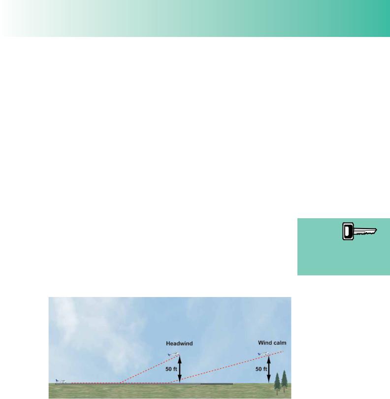
An aircraft will lift off at a certain indicated air speed quoted in the Pilot’s Operating Handbook. Consequently, if a stationary aircraft is pointing into a wind of, say, 15 knots, it will already register an indicated airspeed of 15 knots and be 15 knots closer to its lift-off speed, even though its ground speed is zero. An aircraft whose lift-off speed is 60 knots will, therefore, only have to accelerate to a ground speed of 45 knots in order to get airborne. Therefore, when taking off into wind, the aircraft reaches its lift-off speed in a shorter distance, than if the wind were calm or blowing from a different direction.
Following lift-off, the aircraft’s angle of climb relative to the ground is also steeper, when climbing into wind, than if the wind were calm. This is because the aircraft’s initial angle of climb, which is always close to its maximum angle of climb, is achieved at a given airspeed. Obviously, when fying into a headwind, the corresponding ground speed is lower, so a given climb gradient is always steeper relative to the ground when fying into a headwind.
With a headwind, the 50 ft screen height will, consequently, be achieved over a shorter distance than in calm conditions. The stronger the headwind, the shorter will be the Take-Off Distance Required, as shown in Figure 2.7.
Figure 2.7 Headwinds reduce ground speed for a given indicated air speed and increase initial climb angle, decreasing Take-Off Distance Required.
When calculating Take-Off Distance Required in a headwind, the UK CAArecommends that, as a safety factor, only 50% of the observed headwind component strength be used in the calculation, in order to take into account changes in wind strength and direction. Some take-off performance graphs may have this safety-factor already built in. It is the pilot’s responsibility to confrm whether that is the case or not.
Taking off into
a headwind decreases the
groundspeed
of an aircraft at lift-off and decreases the Take-Off Distance Required.
367
Order: 6026
Customer: Oleg Ostapenko E-mail: ostapenko2002@yahoo.com
Customer: Oleg Ostapenko E-mail: ostapenko2002@yahoo.com
CHAPTER 2: TAKE-OFF
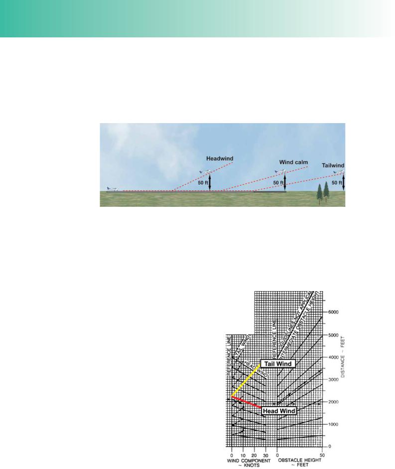
Tailwinds.
If an aircraft were to take off with a tailwind of, say, 5 knots, the aircraft would have to accelerate to 5 knots ground speed before its airspeed began to register. At 5 knots groundspeed, with a 5 knot tailwind, the aircraft’s airspeed would be zero. Airspeed is the critical factor in generating lift force, so with a tailwind the aircraft will evidently have to accelerate to a groundspeed which is greater than the take-off airspeed, thus making the ground run longer.
Figure 2.8 Tailwinds increase the ground speed for a given indicated air speed and reduce the initial climb angle. Take-Off Distance Required is, thus, greater in a tailwind.
Likewise, after lift-off, the aircraft’s groundspeed will remain 5 knots above its airspeed, and, as an aircraft’s achievable angle of climb performance is relative to the air in which the aircraft is fying and not to the ground, with a tailwind the aircraft’s gradient of climb will be shallower with respect to the ground. The aircraft’s obstacle clearance performance will, thus, be degraded in a tail wind and the horizontal distance required for the aircraft to reach the 50 feet screen height will be greater. Take-Off Distance Required, then, will be greater in a tailwind. (See Figure 2.8.)
Even a light tailwind will increase the Take-Off Distance Required very signifcantly, and obstacle clearance may be degraded to such an extent that a safe take-off may not be able to be carried out. For a 5 knot tailwind, Take-Off Distance Required is increased by about 25% (increased by a factor of 1.25). In a 10 knot tailwind Take-Off Distance Required increases by about 155% (increased by a factor of 1.55).
When calculating Take-Off Distance Required in a tailwind, it is recommended that that, as a safety factor, 150% of the observed tailwind component strength be used in the calculation in order to take into account changes in wind strength and direction. Again, some performance graphs include the 150% factor.
Figure 2.9 Most performance graphs include 50% / 150% wind safety factors.
368

ID: 3658
Customer: Oleg Ostapenko E-mail: ostapenko2002@yahoo.com
Customer: Oleg Ostapenko E-mail: ostapenko2002@yahoo.com
CHAPTER 2: TAKE-OFF
Crosswinds.
The wind rarely blows down the runway centre-line, so very frequently a given wind will have a crosswind component as well as a headwind/tailwind component. When entering headwind into any take-off calculation, pilots must ensure that they make an accurate assessment of the wind speed and direction and use the component of the wind which acts along the centre line of the runway, against the direction of take-off. For example, a crosswind blowing at 90° to the runway centre-line will give an aircraft no benefcial headwind component at all, whereas it may well cause the pilot diffculties of controllability during the take-off run because of the tendency of an aircraft to weathercock into wind and for the into-wind wing to lift.
Calculating Headwind Component.
Pilots can calculate headwind components for any given wind direction and strength, using a fight navigation computer. The CD-ROM in the Navigation & Radio Aids volume of this series teaches you how to do that. As a rough guide to assessing headwind components, however, pilots may use the diagram at Figure 2.10.
Figure 2.10 The “Clock” System of estimating Headwind Component. Angles are measured from the aircraft’s lateral axis.
Notice that wind angles are measured with respect to the aircraft’s lateral axis or with respect to a line cutting the runway centre line at 90°. The system illustrated may be memorized by comparing the factors of headwind component to the division of an hour of time. 30° may be compared to 30 minutes; 30 minutes is half an hour, and so 30° of crosswind, measured from the aircraft’s lateral axis, gives a headwind component of half the wind strength. Similarly, 45° gives ¾ of the wind strength as the headwind component, and any angle greater than 60° will effectively give the full wind strength as the headwind component. This system is not 100% accurate, mathematically, but it is very close to that, and may be used to estimate headwind components with a fair degree of accuracy if you do not have a computer or calculator with you.
Tailwind components in a crosswind may be estimated in the same manner.
369
Order: 6026
Customer: Oleg Ostapenko E-mail: ostapenko2002@yahoo.com
Customer: Oleg Ostapenko E-mail: ostapenko2002@yahoo.com
CHAPTER 2: TAKE-OFF
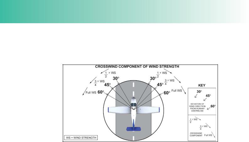
Calculating Crosswind Component.
Pilots can calculate the crosswind component of any given wind direction and strength using a fight navigation computer or they may reasonably accurately assess the crosswind component using the diagram at Figure 2.11.
Figure 2.11 The “Clock” System of estimating Crosswind Component. Angles are measured from the aircraft’s longitudinal axis.
Notice that, here, wind angles are measured with respect to the aircraft’s longitudinal axis or with respect to the runway centre line. As you have just learned, the wind directions may be compared to the division of an hour of time. 30° may be compared to 30 minutes; 30 minutes is half an hour, and so 30° of headwind, measured from the aircraft’s longitudinal axis or the runway centre line, gives a crosswind component of half the wind strength. Similarly, 45° gives ¾ of the wind strength as the crosswind component, and any angle greater than 60° will effectively give the full wind strength as the crosswind component.
Turbulence and Windshear.
Turbulence and windshear will also adversely affect take-off performance.
Firstly, from a practical piloting point of view, in turbulent conditions it is often advisable, during the take-off run, to hold the aircraft on the ground for a slightly longer period of time to provide a better margin above the stall. This will also increase controllability after lift-off, but the penalty is that it will increase the take-off run, too, as well as the overall Take-Off Distance Required.
The possibility of turbulence and windshear must be taken into consideration when working out take-off distances. Windshear is a change in wind velocity (speed and/ or direction) over a very short distance. The presence of windshear can cause sudden fuctuations in airspeed. Hangars, buildings and areas of trees all infuence the direction of the wind near them. In turbulent conditions, windshear and gusts may be signifcant in the lee of obstructions. The vertical components of this type of turbulence will affect climb angle and rate of climb, either benefcially or adversely.
The great danger of the presence of turbulence and windshear is that the effects are unpredictable.
370
ID: 3658
Customer: Oleg Ostapenko E-mail: ostapenko2002@yahoo.com
Customer: Oleg Ostapenko E-mail: ostapenko2002@yahoo.com
CHAPTER 2: TAKE-OFF
Runway Slope.
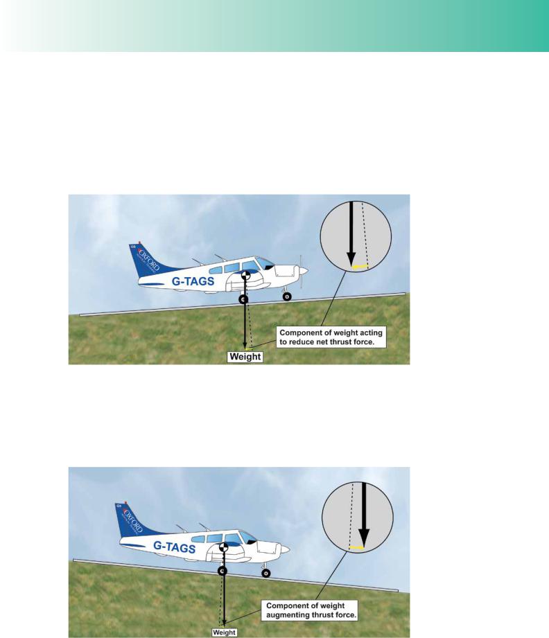
Runway Slope affects take-off distance because, if slope is present, a component of the aircraft’s weight will act along the runway, down the slope.
If an aircraft takes off on a runway which slopes upwards, a component of the aircraft’s weight will act against the direction of motion of the aircraft, reducing the net thrust force developed at the propeller, decreasing acceleration and increasing the take-off run. Obviously the Take-Off Distance Required (to reach the 50 feet screen height) will also be increased.
Figure 2.12 Upslope reduces acceleration owing to a component of weight acting backwards against thrust. This increases the Take-Off Distance Required.
Conversely, if an aircraft takes off on a downwards sloping runway, a component of the aircraft’s weight will act in the direction of take-off, thereby adding to the thrust force developed by the propeller. Taking off on a down-slope, then, will increase acceleration, reduce the take-off run and decrease the overall Take-Off Distance Required.
Figure 2.13 Downslope increases acceleration owing to a component of weight acting forwards to augment propeller thrust force. This reduces Take-Off Distance Required.
371

Order: 6026
Customer: Oleg Ostapenko E-mail: ostapenko2002@yahoo.com
Customer: Oleg Ostapenko E-mail: ostapenko2002@yahoo.com
CHAPTER 2: TAKE-OFF
For every 1% of up-slope the take off distance is increased by 5%, or a factor of 1.05.
No factor is applied for the advantage of a downwards-sloping runway for take-off. A down-slope should be regarded as a bonus when taking off.
Calculating Runway Slope.
The gradient of a slope can be calculated if certain information is available. If a pilot knows the difference in height between the two ends of a runway, the gradient of slope may be found by dividing the difference in height by the runway length (taking care to work in the same units of measurement). For example, a 2 500 feet (760-metre) long runway which is 50 feet (15 metres) higher at one end than the other has a slope gradient of approximately 0.02, or 2%.
Runway Surface.
Most take-off performance graphs and tables assume that certain “associated conditions” apply to the airfeld and aircraft which are the subjet of the take-off performance calculations. One of those associated conditions is, invariably, that the aircraft is operating from a level, paved, dry surface. This is the case for the section of graph that we illustrate in Figure 2.14. If the runway surface conditions differ from these assumptions, allowance must be made for that difference, in takeoff calculations.
Figure 2.14 Performance graph assumptions.
Even on a hard, paved runway, a wet surface will cause an increase in wheel drag. An aircraft taking off on a wet runway will, therefore, accelerate less rapidly leading to an increase in the take-off run and in the overall Take-Off Distance Required. Any puddles of water on the runway would have a very signifcant retarding effect on an aircraft’s acceleration. Taking off through standing water should be avoided.
Of course, many small airfelds have grass strips. Even dry grass will increase wheel drag compared to a take-off on a paved or asphalt runway, again leading to an increase in the take-off run and overall Take-Off Distance Required.
Dry grass can increase Take-Off Distance Required by up to 15% compared to a paved runway. If dry grass is as long as 8 inches (20 cm), Take-Off Distance
372