

ppl_05_e2
.pdfID: 3658
Customer: Oleg Ostapenko E-mail: ostapenko2002@yahoo.com Customer: Oleg Ostapenko E-mail: ostapenko2002@yahoo.com
CHAPTER 13
THE STALL AND SPIN
287

Order: 6026
Customer: Oleg Ostapenko E-mail: ostapenko2002@yahoo.com
Customer: Oleg Ostapenko E-mail: ostapenko2002@yahoo.com
CHAPTER 13: THE STALL AND SPIN
288
ID: 3658
Customer: Oleg Ostapenko E-mail: ostapenko2002@yahoo.com
Customer: Oleg Ostapenko E-mail: ostapenko2002@yahoo.com
CHAPTER 13: THE STALL AND SPIN
STALLING.
The Stalling Angle of Attack.
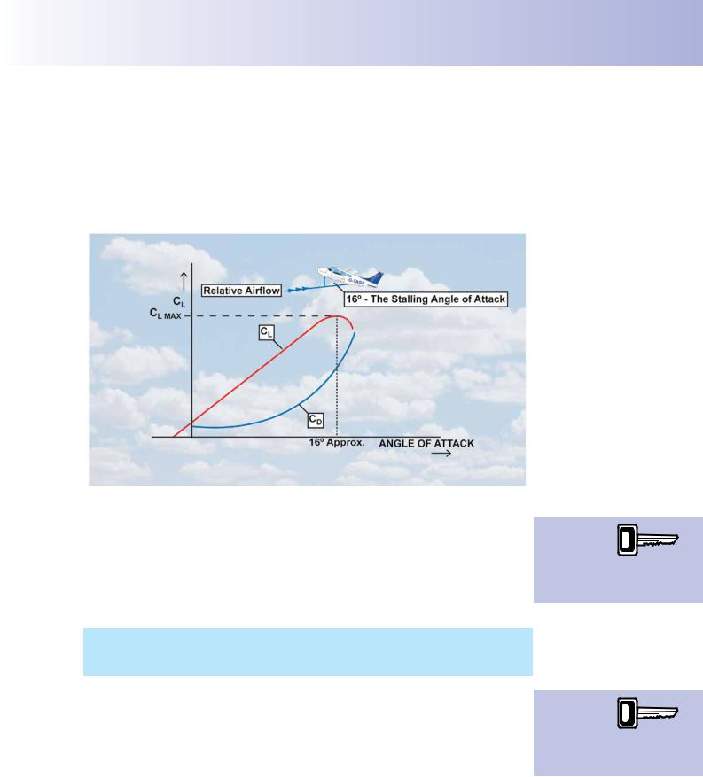
You learnt in the chapter on Lift, that the coeffcient of lift, CL, increases with increasing angle of attack, until CL reaches a maximum, at about 16° angle of attack for the type of wing used on most light aircraft. Above this angle, CL decreases sharply. This situation is illustrated by the red CL line in the graph at Figure 13.1.
Figure 13.1 At the stalling angle of attack, CL decreases sharply but CD carries on increasing.
As the lift force developed by a wing is directly proportional to CL, (Lift = CL ½ ρ v2 S), we can see from Figure 13.1 that, whereas for small angles of attack any increases in angle of attack will produce an increase in lift force, when a certain angle is reached (16° in the diagram), any further increase in angle of attack will result in a reduction in the lift force. This angle is called the stalling angle of attack. (Note that Figure 13.1 shows that the coeffcient of drag, CD, continues to rise, beyond the stalling angle of attack.)
It is important to realise that the speed at which a wing is moving through the air makes no difference to the angle of attack at which the wing stalls. An aerofoil stalls at a given angle of attack, not at a given speed.
Given that a wing stalls at a given angle of attack and not at a given airspeed, it is interesting to consider why the Pilot’s Operating Handbook contains a stalling speed for an aircraft. We will return to that point in a moment. But frst, let us look a little more closely at what happens at the point of stall.
The Coefficient
of Lift is at a maximum value immediately
prior to the stalling angle of attack being reached.
An aircraft will
stall when the angle of attack
reaches the
critical angle, regardless of airspeed.
289

Order: 6026
Customer: Oleg Ostapenko E-mail: ostapenko2002@yahoo.com
Customer: Oleg Ostapenko E-mail: ostapenko2002@yahoo.com
CHAPTER 13: THE STALL AND SPIN
The Point of Stall.
As we have established, an aircraft’s wing will always stall at the same angle of attack. As the angle of attack (a) increases, the pressure pattern around the wing changes and the centre of pressure (CP) moves forward, as depicted in Figure 13.2. The CP is at its most forward point just before the stalling angle of attack is reached. This situation is illustrated in Figure 13.2 at a = 15°.
Figure 13.2 Changes in pressure pattern and lift force with an increasing angle of attack.
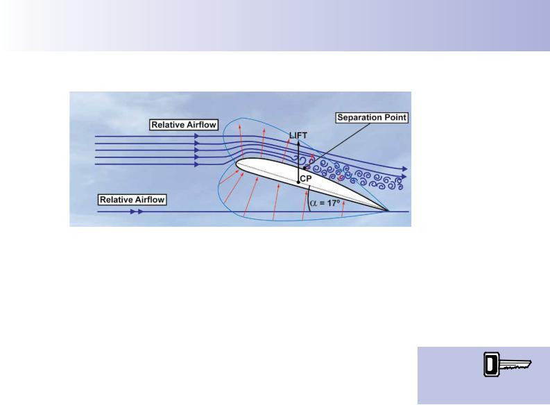
As detailed in Figure 13.3, as the CP moves forward, the pressure distribution around the wing is such that the airfow over the wing meets an increasingly rising pressure as it moves towards the wing’s trailing edge. The boundary layer, consequently, begins to thicken, becomes more turbulent, and then separates from the upper surface of the wing. As the angle of attack continues to increase, the separation point moves forward.
Figure 13.3 Just before the stall, the airflow meets increasingly rising pressure.
290
ID: 3658
Customer: Oleg Ostapenko E-mail: ostapenko2002@yahoo.com
Customer: Oleg Ostapenko E-mail: ostapenko2002@yahoo.com
CHAPTER 13: THE STALL AND SPIN
Figure 13.4 As the stalling angle of attack is reached and exceeded, most of the airflow separates from the wing. The CP moves rearwards and lift reduces abruptly.
At an angle of attack, above approximately 16°, most of the airfow separates from the wing upper surface. The CP moves sharply rearwards and the lift force decreases abruptly and is no longer suffcient to balance the weight of the aircraft. (See Figure 13.4). The wing has stalled. At the stall, the controls lose a great deal of their effectiveness and the aircraft loses height rapidly, until the aircraft is recovered from the stall.
The Straight Flight Stalling Speed.
In straight fight, the stall occurs at an indicated airspeed which is defned in the Pilot’s
Operating Handbook (POH) as the stalling speed. But we have just established that a wing stalls at a given angle of attack, not at a given airspeed. So what is meant by the stalling speed contained in the POH?
In order to answer this question, we will assume that an aircraft whose wing stalls at an angle of attack of 16° is fying straight and level at 90 knots, with the relative airfow meeting the wing at a typical cruising angle of attack of 4°. As the aircraft is in straight fight, the lift produced by the wings balances the aircraft’s weight exactly.
Now, you will recall from the lift formula, Lift = CL ½ ρ v2 S, that the factors contributing to the generation of this lift force, which just balances the aircraft’s weight, are: the density of the air, ρ, the area of the lifting surfaces, S, the aircraft’s airspeed, v, and the coeffcient of lift, CL, which represents wing camber and confguration, as well as angle of attack.
If the pilot now takes off all power, which in level fight is providing the speed of the airfow, v, the value of v in the lift equation reduces, leading to a reduction in the lift force. Consequently, as lift just balanced weight before the pilot reduced the power, unless the pilot takes some other action, weight will be greater than lift and the aircraft will begin to lose height.
If the pilot wishes to maintain height, he can choose to maintain the lift equal to weight by increasing the value of CL. The only way the pilot can increase CL without lowering the faps is by moving the control column rearwards to increase the wing’s angle of attack.
If he chooses to take this action, airspeed, v, will decrease further because an aircraft cannot continue to fy level at a constant speed unless the propeller produces suffcient thrust to counteract drag, induced drag having also risen with increasing angle of attack. With the throttle closed, of course, thrust is effectively zero.
An aircraft can be stalled in any attitude regardless of speed.
291

Order: 6026
Customer: Oleg Ostapenko E-mail: ostapenko2002@yahoo.com
Customer: Oleg Ostapenko E-mail: ostapenko2002@yahoo.com
CHAPTER 13: THE STALL AND SPIN
As the airspeed decreases, the lift will necessarily also reduce (Lift = CL ½ ρ v2 S) unless lift is maintained equal to weight by the pilot further increasing the angle of attack (and, thus, CL) through a continued rearward movement of the control column. And, of course, because of the continuing increase in angle of attack, airspeed will further decrease and induced drag increases, and so forth and so on until the angle of attack reaches the stalling angle of attack, and the wing stalls, causing the aircraft to lose height rapidly until the pilot recovers from the stall.
When the stall occurs, in this straight fight scenario, the airspeed will have reduced to a certain value which, in the Pilot’s Operating Handbook, is given as the basic stalling speed for this particular aircraft type. This quoted stalling speed only applies to the speed at which the wing reaches the stalling angle when the pilot attempts to keep the aircraft fying straight and level without any thrust from the propeller; (that is, with the throttle closed).
An aircraft’s basic stalling speed quoted in the Pilot’s Operating Handbook is, therefore, the speed at which the aircraft stalls in straight and level unaccelerated
(i.e. at 1g) fight, power off, with the C of G at its forward limit, and at maximum all-up weight. (These factors are explained later in this chapter).
The very term stalling speed is misleading, because of the suggestion contained within the term that the stall is dependent on airspeed. This is not the case. The aircraft will stall over a range of speeds provided that the stalling angle of attack is reached at the given speed. Let us look into this statement more deeply.
FACTORS AFFECTING THE STALL.
The Effect of Weight on the Stall.
We have established that a given wing will always stall at the same angle of attack, which is approximately 16° for a typical light aircraft aerofoil cross section. The stalling angle of attack can be defned as that angle of attack at which the lift coeffcient, CL, reaches a maximum, and beyond which CL will decrease sharply. We may represent this maximum value of CL at the point of the stall as CL MAX.(See Figure 13.1).
Therefore, the lift equation, which defnes the lift force at the point of stall becomes:
Lift = CL MAX ½ ρ v2 S
Also, at the point of the stall, from straight and level fight, immediately before the angle of attack is further increased causing the stall to occur, lift must equal weight. It follows, then, that, for the situation just before the stall occurs, in straight and level fight, we may re-write the above equation as:
Weight = Lift = CL MAX ½ ρ (vstall)²S
The stall speed increases as aircraft weight increases.
In this equation, (applied to the point of stall from straight and level fight, remember), v now represents the stalling speed quoted in the Pilot’s Operating Handbook, so we have represented stalling speed as vstall.
Now, as CL MAX is constant, for a given wing (because a given wing will always stall at the same angle of attack) and taking wing area, S, to be also constant (i.e. discounting use of fap), we can see that any increase in aircraft weight will require an increase in vstall to make the lift equation balance. Conversely, a decrease in weight would require a decrease in vstall to make the equation balance.
It follows, then, from the lift equation, that a heavier aircraft will stall at a higher airspeed than a more lightly loaded aircraft.
292
ID: 3658
Customer: Oleg Ostapenko E-mail: ostapenko2002@yahoo.com
Customer: Oleg Ostapenko E-mail: ostapenko2002@yahoo.com
CHAPTER 13: THE STALL AND SPIN
Manoeuvring with Varying Load Factors.
We have seen that the lift equation applied to the point of stall, from straight and level fight, can be written as:
Weight = Lift = CL MAX ½ ρ (vstall)² S where vstall is the aircraft’s straight and level stall speed.
But, as you learnt in the chapter on ‘Flight Forces’, in manoeuvres such as turning fight, lift needs to be greater than the weight of the aircraft.
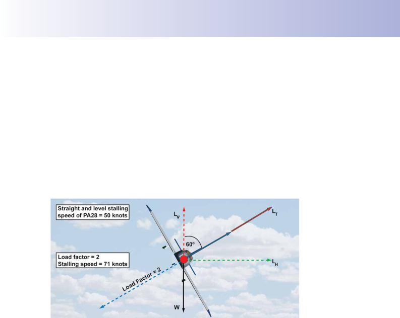
In a 60°-banked level turn, for instance, the lift force required to generate the necessary centripetal force for the turn, and, at the same time, continue to balance the aircraft’s weight in order to maintain level fight in the turn, is twice as great as the aircraft’s weight. During the turn, the inertial reaction to this increase in lift is equal in magnitude to the increased lift, and acts in the opposite direction to the line of action of the lift, as depicted in Figure 13.5.
Figure 13.5 A 60º banked turn. The lift required for the turn is twice its straight fight value,
Load Factor is 2, and the stalling speed is 71 knots.
The complete aircraft, including its occupants, will be subjected to this inertial reaction which is known as load factor. The load factor acting on the aircraft during a 60°-banked turn is 2, because the lift force is twice its value for level fight, and the aircraft and its occupants sense this load factor as an apparent increase in weight by a factor of 2. In popular parlance, the pilot will say that he is pulling 2g.
We are now in a position to refer once more to the lift equation and to apply it to turning fight to see what it has to teach us in terms of stalling speed in the turn. As we have learnt, immediately before the stall occurs:
Lift = CL MAX ½ ρ (vstall)² S
293
Order: 6026
Customer: Oleg Ostapenko E-mail: ostapenko2002@yahoo.com
Customer: Oleg Ostapenko E-mail: ostapenko2002@yahoo.com
CHAPTER 13: THE STALL AND SPIN
During manoeuvres,
stall speed increases as
load factor increases.
Now, in the 60°- banked level turn that we are considering, we have learnt that, because the load factor = 2, lift must be twice the value of that required for straight and level fight. So, from the lift equation we can deduce that as lift is increased by a factor of 2 in the 60° turn, and as CL MAX, ½, ρ, and S are all constants, (vstall)², which represents the aircraft’s airspeed at which the aircraft stalls in straight and level fight, must also increase by a factor of 2. We can see immediately, then, that an aircraft’s stalling speed increases in a turn, because of the increase in load factor.
And, of course, the stalling speed is getting higher because, with the increased load factor, the relative airfow meets the wing at the stalling angle of attack
(16° for a conventional aerofoil section) at a higher speed than if the aircraft were in level fight.
But by how much does the stalling speed increase in a turn?
Well, if (vstall)² has doubled in the 60°-banked level turn, then, for the 60°- banked turn:
An aircraft’s stalling
speed for any manoeuvre is
the straight-flight stall speed multiplied by the square root of the load factor.
vstall has increased by a factor of stt2
In other words, vstall has increased by a factor of 1.414
In a 60°-banked turn, then, stalling speed increases by a factor of 1.414 times the straight and level stalling speed.
Now, in the lift equation, vstall is the True Airspeed (TAS) at the stall. But, as you learn elsewhere in this book, TAS is directly proportional to the Indicated Airspeed (IAS) that the pilot reads from the Airspeed Indicator. Therefore, in the 60° - banked turn, if the stalling speed, expressed as TAS, has increased by a factor of 1.414, the stalling speed expressed as IAS has also increased by the same factor.
So if we know an aircraft’s stalling speed from straight fight, it is easy to calculate its stalling speed in a turn. For instance, if an aircraft’s straight fight stalling speed is
50 knots, indicated, its stalling speed in a 60°-banked level turn will be (50 × 1.414) knots, which is approximately 70 knots, indicated.
Furthermore, if we know the load factor to which an aircraft is subjected during a turn, or in the course of any other manoeuvre, and if we also know the aircraft’s straight-fight stalling speed (given in the Pilot’s Operating Handbook), we can easily calculate the stalling speed for the manoeuvre, from the equation:
vstall(m) = vstall(SF) × stttttttttttttttttLoad Factor
where vstall(m) is the indicated stalling speed for the particular manoeuvre, and vstall(SF) is the stalling speed from straight and level fight.
We can also immediately deduce that any manoeuvre which increases the load factor on an aircraft will also increase its stalling speed during the manoeuvre. So an aircraft pulling out of a high speed dive will stall at a speed considerably higher than the straight fight stalling speed; in other words, its wing will reach the stalling angle of attack during the pull-out while the aircraft is still fying at high speed. This situation is depicted in Figure 13.6.
294

ID: 3658
Customer: Oleg Ostapenko E-mail: ostapenko2002@yahoo.com
Customer: Oleg Ostapenko E-mail: ostapenko2002@yahoo.com
CHAPTER 13: THE STALL AND SPIN
For example, if, during the pull-out manoeuvre depicted in Figure 13.6, the load factor were to reach 4 (that is, if the aircraft “pulled 4g”), the equation in the blue box, above, tells us that aircraft would stall at a speed twice as high (stt4) as that published in the Pilot’s Operating Handbook. So, if the aircraft’s published stalling speed were 50 knots IAS, it would stall at 100 knots IAS, while pulling out from the dive that we are considering.
Figure 13.6 An aircraft will stall at any speed when its wing reaches the stalling angle of attack.
Figure 13.7 Load Factors in the turn for various angles of bank (applies to all aircraft).
Figure 13.7 shows the load factor to which an aircraft is subjected for turns at various angles of bank. Note that the load factors shown apply to all aircraft, at the angles of bank indicated. So, if you know the straight fight stalling speed vstall(SF) for a particular aircraft, you can easily calculate its stalling speed for any angle of bank, by noting the corresponding load factor for that angle of bank and applying the equation:
vstall(m) = vstall(SF) × stttttttttttttttttLoad Factor
Figure 13.8 overleaf gives stalling speeds for turns of various angles of bank. The speeds in the graph overleaf are based on a stalling speed from straight and level fight of 50 knots, indicated.
295

Order: 6026
Customer: Oleg Ostapenko E-mail: ostapenko2002@yahoo.com
Customer: Oleg Ostapenko E-mail: ostapenko2002@yahoo.com
CHAPTER 13: THE STALL AND SPIN
Figure 13.8 Stalling speeds for various angles of bank based on a straight-flight stalling speed of 50 knots.
You should note that only aircraft ftted with very powerful engines are able to fy level turns at angles of bank above 70°. The engine needs to be powerful in order to overcome the high levels of induced drag at the angles of attack necessary to fy very steep level turns. Such aircraft also need to have structures which can support the stress of the high load factors generated by very steep turns. Training aircraft rarely execute turns above 60° angle of bank. 45° angle of bank will most probably be the steepest turn that you will be required to fy in PPL training.
For your general interest, we include in the blue box the mathematics required to derive the formula for calculating load factor for a turn of any angle of bank, q.
Figure 13.9 Calculating load factor from angle of bank.
The Effect of Altitude on Stall Speed.
In the lift equation, Lift = CL½ρv²S, v represents the aircraft’s True Airspeed (TAS).
So, immediately before the stall where Lift = CL MAX ½ ρ(vstall)²S, vstall is also a
TAS.
296