Добавил:
Опубликованный материал нарушает ваши авторские права? Сообщите нам.
Вуз: Предмет: Файл:

ppl_05_e2

.pdf
Скачиваний:
3773
Добавлен:
26.01.2018
Размер:
16.26 Mб
Скачать

ID: 3658

Customer: Oleg Ostapenko E-mail: ostapenko2002@yahoo.com

Customer: Oleg Ostapenko E-mail: ostapenko2002@yahoo.com

CHAPTER 2: TAKE-OFF QUESTIONS

Representative PPL - type questions to test your theoretical knowledge of Take-off.

1.If the density of the atmosphere is reduced, the take-off distance required will be:

a.increased

b.decreased

c.unaffected

d.reduced with a wind

2.What effect will a higher aircraft mass have on the rotate speed and take off safety speed?

a.It will decrease both speeds

b.It will increase rotate speed and decrease take off safety speed

c.It will increase both speeds

d.It will decrease rotate speed and increase take off safety speed

3.That part of a runway surface which is used for normal operations during take off, excluding any clearway or stopway, is referred to as:

a.the Take-Off Run Available (TORA)

b.the Accelerate-Stop Distance Available (ASDA)

c.the Take-Off Distance Available (TODA)

d.the Emergency Distance Available (EMDA)

4.Complete the following statement as accurately as possible using one of the options a), b), c) or d).

If the density of the air increases the effect will be:

a.to increase the take-off distance required

b.to increase the take-off run

c.to decrease the take-off distance required

d.to decrease the indicated airspeed at lift-off

5.Complete the following statement as accurately as possible using one of the options, a), b), c) or d).

The main reason for taking off into wind is to:

a.increase the take-off distance required

b.decrease the take-off distance available

c.increase the ground speed of the aircraft at lift-off

d.decrease the ground speed of the aircraft at lift-off and to decrease the Take-Off Distance Required

383

Order: 6026

Customer: Oleg Ostapenko E-mail: ostapenko2002@yahoo.com

Customer: Oleg Ostapenko E-mail: ostapenko2002@yahoo.com

CHAPTER 2: TAKE-OFF QUESTIONS

6.Complete the following statement as accurately as possible using one of the following options: a), b), c) or d).

During take-off, the use of the manufacturer’s recommended take-off flap setting:

a.compared to zero flap, will increase the length of the take-off run and obstacle clearance performance

b.compared to zero flap, will decrease the take-off run required but reduce obstacle clearance performance

c.compared to zero flap, will increase the indicated airspeed at which the aircraft can lift-off

d.compared to zero flap, will ensure a steeper angle of climb after liftoff

7 .

Complete the following statement accurately using one of the options: a), b),


c) or d).

When the density of the atmosphere is relatively low, the resulting reduction in:

a.thrust and drag has no apparent effect on the take-off distance required

b.both lift and engine power will require a longer take-off distance

c.drag will permit the use of greater flap angles

d.drag offsets the loss of engine power giving improved acceleration

8.The horizontal distance covered during take-off, from brakes-release to the 50 feet screen height, and which includes any stopway or clearway, is referred to as:

a.the Take-Off Run Available (TORA)

b.the Accelerate-Stop Distance Available (ASDA)

c.the Take-Off Distance Available (TODA)

d.the Emergency Distance Available (EMDA)

9.That part of a take-off strip which includes the Take-Off Run Available and the stopway, is referred to as:

a.the Take-Off Run Available (TORA)

b.the clearway

c.the Take-Off Distance Available (TODA)

d.the Accelerate-Stop Distance Available (ASDA) or Emergency Distance Available (EDA)

384

ID: 3658

Customer: Oleg Ostapenko E-mail: ostapenko2002@yahoo.com

Customer: Oleg Ostapenko E-mail: ostapenko2002@yahoo.com

CHAPTER 2: TAKE-OFF QUESTIONS

10.What name is given to the distance which comprises Take-Off Run Available (TORA) and any clearway?

a.Emergency Distance Available (EMDA)

b.Take-Off Distance Required (TODA)

c.Accelerate-Stop Distance Available (ASDA)

d.Take-Off Distance Available (TODA)

11.A 15 knot wind at 60° off the runway heading gives a headwind component of approximately:

a.8 knots

b.14 knots

c.12 knots

d.3 knots

12.A 15 knot wind at 60° off the runway heading gives a crosswind component of approximately:

a.8 knots

b.14 knots

c.12 knots

d.3 knots

Question

1

2

3

4

5

6

7

8

9

10

11

12


Answer


The answers to these questions can be found at the end of this book.

385

Order: 6026

Customer: Oleg Ostapenko E-mail: ostapenko2002@yahoo.com Customer: Oleg Ostapenko E-mail: ostapenko2002@yahoo.com

386

ID: 3658

Customer: Oleg Ostapenko E-mail: ostapenko2002@yahoo.com Customer: Oleg Ostapenko E-mail: ostapenko2002@yahoo.com

CHAPTER 3

CLIMB

387

Order: 6026

Customer: Oleg Ostapenko E-mail: ostapenko2002@yahoo.com

Customer: Oleg Ostapenko E-mail: ostapenko2002@yahoo.com

CHAPTER 3: CLIMB

388

ID: 3658

Customer: Oleg Ostapenko E-mail: ostapenko2002@yahoo.com

Customer: Oleg Ostapenko E-mail: ostapenko2002@yahoo.com

CHAPTER 3: CLIMB

INTRODUCTION.

An aircraft’s ability to achieve a satisfactory angle and rate of climb is an important aspect of its overall performance. It is obviously effcient to be able to climb rapidly to the pilot’s chosen cruising altitude, but it is also desirable that an aircraft should be able to climb steeply in order to achieve safe obstacle clearance performance as well as to keep noise pollution to a minimum. We will begin by examining angle of climb.

ANGLE OF CLIMB.

Figure 3.1 depicts an aircraft in un-accelerated straight and level fight. Lift balances weight and thrust balances drag, so all four forces are in equilibrium. Airspeed and altitude are constant.

Figure 3.1 Straight and level fight with the four principal fight forces in equilibrium (simplifed).

If the pilot now raises the nose, without increasing thrust, the disposition of forces will be as shown in Figure 3.2.

Figure 3.2 If the pilot attempts to climb without increasing thrust, the aerodynamic drag plus the component of the aircraft’s weight acting rearwards are now greater than thrust. The aircraft will, therefore, lose speed.

389

Order: 6026

Customer: Oleg Ostapenko E-mail: ostapenko2002@yahoo.com

Customer: Oleg Ostapenko E-mail: ostapenko2002@yahoo.com

CHAPTER 3: CLIMB

Figure 3.2 shows that the aircraft will begin to climb, but a component of the aircraft’s weight now acts rearwards along the longitudinal axis in the same direction as the aerodynamic drag. This component is called weight apparent drag. The rearward acting forces are now, consequently, greater than the forward acting thrust force. The end result, depending on the pitch attitude selected by the pilot, would be either that the aircraft continues to climb at a lower airspeed, or the aircraft may eventually stall.

In order to maintain his original speed in the climb, therefore, the pilot opens the throttle to increase the thrust developed at the propeller and so balance the rearwards acting weight component of the aircraft (the weight apparent drag). The extra thrust that the pilot has applied is excess thrust that the engine has available over and above the thrust required to maintain level fight at the same speed. (See Figure 3.3.)

The greater the amount of

excess thrust available, the

greater can be the angle of climb.

Figure 3.3 Forces in a steady climb showing excess thrust balancing weight apparent drag.

You have learnt in Principles of Flight that in order to maintain level fight, the thrust required from the propeller must exactly counteract aerodynamic drag. In level fight, then, any extra thrust which is available from the engine-propeller combination can be used to climb the aircraft, if the pilot wishes.

It follows then that, for a given airspeed, the greater the excess thrust available in the engine-propeller combination, over and above the thrust required to maintain level fight at that airspeed, the steeper the aircraft will be able to climb at that airspeed. The steepest angle of climb will be achieved by climbing at maximum power at the level fight speed at which the extra thrust available for the climb is at a maximum.

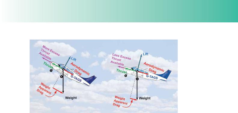
This principle is depicted by Figure 3.4 which shows two aircraft, each at its maximum angle of climb; (Note, though, that the force arrows are not drawn to scale.) The aircraft on the left has attained a steeper angle of climb because, for its speed, weight and confguration, in the climb, it had more excess thrust available at that speed when it was in straight and level fight.

390

ID: 3658

Customer: Oleg Ostapenko E-mail: ostapenko2002@yahoo.com

Customer: Oleg Ostapenko E-mail: ostapenko2002@yahoo.com

CHAPTER 3: CLIMB

Figure 3.4 The steepest angle of climb will be achieved by climbing at maximum power at the level-fight speed at which the excess thrust available is a maximum.

There are several factors then which affect how much extra thrust is available for the climb, over and above the thrust required for level fight. The speed factor has already been mentioned, and we discuss speed in more detail, below. Other factors which affect angle of climb are aircraft weight, aircraft confguration (e.g. position of faps and undercarriage), air density and, as far as the angle of climb relative to the ground is concerned, the strength of headwind component. These latter factors will mentioned latter in this chapter.

Speed and Best Achievable Angle of Climb.

Let us look at some fnal points about the relationship between speed and angle of climb.

As we have seen the angle of climb at a given speed is a function of the excess thrust available from the engine-propeller combination over and above the thrust required to fy straight and level at that speed. There will of course be only one level fight speed at which the excess thrust, still able to be developed by the propeller, is at a maximum. This will be the aircraft’s best angle of climb speed, known as VX.

Jet-powered aircraft will achieve their best angle of climb at a speed where drag is minimum. (Jet fghters capable of producing more thrust than they weigh, such as the Harrier, can, of course, climb vertically, and actually accelerate in the vertical climb.)

But, as you learnt in Principles of Flight, in the case of an aircraft driven by a fxedpitch propeller, the amount of thrust produced decreases with airspeed because propeller-blade angle of attack also decreases with airspeed. An aircraft with a fxedpitch propeller, therefore, produces its maximum thrust at a lower airspeed than the speed for minimum drag. By the time such an aircraft has reached minimum drag speed, thrust has decreased considerably, even though engine power has increased. Therefore, the speed for maximum angle of climb (VX) for a simple light aircraft is lower than the speed for minimum drag.

391

Order: 6026

Customer: Oleg Ostapenko E-mail: ostapenko2002@yahoo.com

Customer: Oleg Ostapenko E-mail: ostapenko2002@yahoo.com

CHAPTER 3: CLIMB

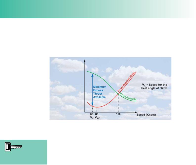
The graph at Figure 3.5 depicts the relationship (for a representative light aircraft) between the speed in level fight and two other parameters: the thrust required to maintain level fight at that speed and the total thrust available from the propeller at that speed. The thrust required curve is taken from the total drag curve for the aircraft because, as you already know, thrust required to maintain level fight must be equal to drag.

VX is the

speed to fy for the best angle of

climb. VX for a Cessna 152 is about 65 knots.

Figure 3.5 Climb angle or gradient is dependent on Excess Thrust Available. Maximum excess thrust available will give maximum angle or gradient of climb. Vx is defned as the speed for best angle or gradient of climb.

Examining the graph, we see that the maximum amount of excess thrust available for the climb is found where the distance between the thrust available and the thrust required curves is the greatest, The corresponding speed on the graph’s horizontal axis is the speed, VX at which the greatest angle of climb is achieved when maximum power is applied. VX, then, is the speed to fy for the best angle of climb.

In a light aircraft such as the Cessna 152, VX will be about 65 knots.

At any other speed than VX, you can see that the excess thrust available reduces; so for any other speed than VX the angle of climb will also reduce.

Forces in the Climb.

In a steady climb, at constant angle of climb and constant speed, the forces of thrust, drag, lift and weight are in equilibrium, just as they are in level fight. However, in the climb, the weight and aerodynamic drag of the aircraft are balanced by a combination of lift and thrust. (See Figure 3.6.) An interesting phenomenon that you should note is that, because, in a steady climb, the total thrust is greater than aerodynamic drag, the lift force itself is less than the aircraft’s weight.

For a light aircraft, at typical light aircraft angles of climb, the lift will be only a little less than the weight. And, of course, as the climb is initiated with the nose of the aircraft raised to the climbing attitude as full power is applied, the lift force will momentarily increase. But as soon as the aircraft is established in the climb, lift reduces to a little below the value of weight.

392

Соседние файлы в предмете [НЕСОРТИРОВАННОЕ]