

AT-3 R100 POH
.pdf“AERO” Sp. z o.o. |
SECTION 7 |
AT-3 R100 |
DESCRIPTION OF THE AEROPLANE |
|
AND ITS EQUIPMENT |
Section 7
DESCRIPTION OF THE AEROPLANE
AND ITS EQUIPMENT
|
Page |
|
7.1. Introduction ............................................................................... |
7-2 |
|
7.2. Airframe .................................................................................... |
7-2 |
|
7.2.1. Fuselage ............................................................................ |
7-2 |
|
7.2.2. Wings ................................................................................. |
7-3 |
|
7.2.3. Slab tail .............................................................................. |
7-4 |
|
7.2.4. Fin and rudder.................................................................... |
7-5 |
|
7.3. Flight control ............................................................................. |
7-6 |
|
7.3.1. Control of the ailerons ........................................................ |
7-6 |
|
7.3.2. Control of the wing flaps..................................................... |
7-7 |
|
7.3.3. Control of the elevator........................................................ |
7-8 |
|
7.3.4. Control of the trim & balancing tab..................................... |
7-9 |
|
7.3.5. Control of the rudder ........................................................ |
7-10 |
|
7.4. Instrument panel ..................................................................... |
7-11 |
|
7.5. Landing gear system .............................................................. |
7-15 |
|
7.5.1. Brake system ................................................................... |
7-15 |
|
7.5.2. Parking brake ................................................................... |
7-17 |
|
7.6. Seats and seat belts ............................................................... |
7-20 |
|
7.7. Luggage compartment............................................................ |
7-21 |
|
7.8. Canopy ................................................................................... |
7-22 |
|
7.9. Power unit............................................................................... |
7-23 |
|
7.9.1. Engine .............................................................................. |
7-23 |
|
7.9.2. Propeller........................................................................... |
7-23 |
9 |
|
|
|
7.10. Fuel system .......................................................................... |
7-24 |
|
7.11. Pitot and static pressure systems ......................................... |
7-26 |
|
7.12. Electric system...................................................................... |
7-27 |
|
7.13. Aeroplane equipment............................................................ |
7-29 |
|
7.13.1.Ventilation and cabin heating………………………………..7-29
7.13.2.Carburettor heating system………………………………….7-30
7.13.3.Air intake covers ...............………………………………….7-31
JULY, 2010 |
Page 7-1 |
|
AEROPLANE FLIGHT MANUAL |

SECTION 7 |
“AERO” Sp. z o.o. |
DESCRIPTION OF THE AEROPLANE |
AT-3 R100 |
AND ITS EQUIPMENT |
|
7.1. Introduction
This Section contains a description of the aeroplane and of its equipment.
7.2. Airframe
7.2.1. Fuselage
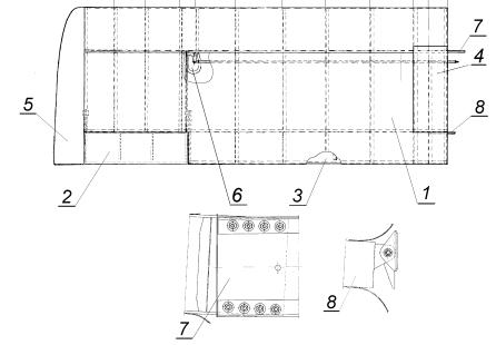
The fuselage, made of duralumin sheet, has a rectangular section, open in the area of the cabin. In the rear the fuselage passes fluently into the fin, being an integral part. The sections between canopy and fuselage, as well as those between fuselage and fin are made of epoxy-fibreglass composite.
Fuselage
1.Fire wall
2.Upper fuel tank cover
3.Canopy
4.Canopy-fuselage fairing made of epoxy-fibreglass
5.Fuselage-fin fairing made of epoxy-fibreglass
6.Fin
7.Ferules of the rudder and the elevator
8.Fuselage frame
Page 7-2 |
SEPTEMBER, 2004 |
|
AEROPLANE FLIGHT MANUAL |
“AERO” Sp. z o.o. |
SECTION 7 |
AT-3 R100 |
DESCRIPTION OF THE AEROPLANE |
|
AND ITS EQUIPMENT |
7.2.2. Wings |
|
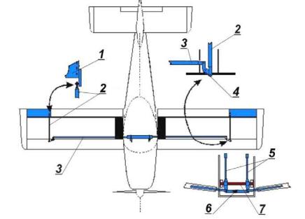
The wings are made of aluminium and are connected to the fuselage by means of the main and of the rear spars. The ailerons and the wing flaps are of similar design are connected to the wing by means of flat hinges. Wing tips made of of epoxy-fibreglass.
Wing
1.Wing frame
2.Aileron
3.Flap
4.Wing-walk surface
5.Wing tip
6.Inspection hatch
7.Main spar
8.Rear spar
SEPTEMBER, 2004 |
Page 7-3 |
AEROPLANE FLIGHT MANUAL |
|

SECTION 7 |
“AERO” Sp. z o.o. |
DESCRIPTION OF THE AEROPLANE |
AT-3 R100 |
AND ITS EQUIPMENT |
|
7.2.3. Slab tail
The tail plane is a slab tail design with a structure similar to the wing, mass balanced, hinged at two points. The trim & balancing tab are contained within the contour of the tail plane.
Slab tail
1.Structure of the slab tail
2.Trim and balancing tab
3.Balancing weight
4.Slab tail fittings
5.Trim and balancing tab flat hinges
6.epoxy-fibreglass tips
Page 7-4 |
SEPTEMBER, 2004 |
|
AEROPLANE FLIGHT MANUAL |

“AERO” Sp. z o.o. |
SECTION 7 |
AT-3 R100 |
DESCRIPTION OF THE AEROPLANE |
|
AND ITS EQUIPMENT |
7. 7.2.4. Fin and rudder
The vertical tail unit consists of fin and rudder. The fin is an integral part of fuselage structure.
Fin and rudder
1.Rudder
2.Anti-collision strobe
3.Rudder mountings
4.Slab tail fittings
5.Lower rudder fitting
SEPTEMBER, 2004 |
Page 7-5 |
AEROPLANE FLIGHT MANUAL |
|
SECTION 7 |
“AERO” Sp. z o.o. |
DESCRIPTION OF THE AEROPLANE |
AT-3 R100 |
AND ITS EQUIPMENT |
|
7.3. Flight control |
|
This section contains a description of the control mechanisms of the wing flaps, the ailerons, the elevator, the trim & balancing tab and of the rudder.
7.3.1. Control of the ailerons
The ailerons are located at the trailing edge of the outboard wing part, between the wing flaps and the wingtips. The scheme of the control mechanism of the ailerons is shown below.
Control of the ailerons
1.Aileron
2.Push rods
3.Push rods
4.Angle lever
5.Control sticks
6.Push rods
7.Torsion tube
Page 7-6 |
SEPTEMBER, 2004 |
|
AEROPLANE FLIGHT MANUAL |
“AERO” Sp. z o.o. |
SECTION 7 |
AT-3 R100 |
DESCRIPTION OF THE AEROPLANE |
|
AND ITS EQUIPMENT |
1. Control of the wing flaps
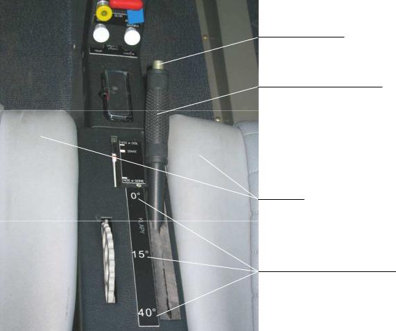
The wing flaps which are of crocodile type (split flaps) are located below the trailing edge of the wing, between the fuselage and the ailerons. The wing flap control lever (see the illustration below) is located in the cabin, on the console, between the seats. This lever is fitted with a knob, which is to release the flap-retaining pin and enables the flap to be set in either of its three positions. In the extreme forward position of the lever the flap is set to GK = 0 .
In the middle position of the lever the flap is set to GK = 15 and in the extreme rear, the setting is GK = 40 .
The wing flap control lever transmits its movement to the flaps via push rod, torsion tube and the two pins.
Releasing knob
Wing flap control lever
Seats
Marking of the flap setting
SEPTEMBER, 2004 |
Page 7-7 |
AEROPLANE FLIGHT MANUAL |
|
SECTION 7 |
“AERO” Sp. z o.o. |
DESCRIPTION OF THE AEROPLANE |
AT-3 R100 |
AND ITS EQUIPMENT |
|
7.3.3. Control of the elevator
The slab tail elevator is fixed to the spar of the fin. The scheme of the elevator control is shown in the illustration below.
Control of the elevator
1.Control stick
2.Torsion tube
3.Short push rod
4.Connecting lever
5.Long push rod
6.Slab tail arm
Page 7-8 |
SEPTEMBER, 2004 |
|
AEROPLANE FLIGHT MANUAL |
“AERO” Sp. z o.o. |
SECTION 7 |
AT-3 R100 |
DESCRIPTION OF THE AEROPLANE |
|
AND ITS EQUIPMENT |
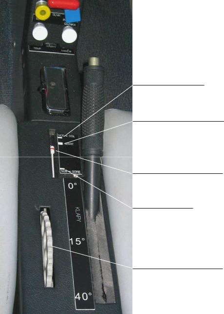
7.3.4. Control of the trim/balancing tab
The trim & balancing tab is fixed to the trailing edge of the slab tail elevator is driven by torsion shaft, self locking screw gear and assembly of levers and pushrods .
The illustration below shows the control wheel of the tab and the tab setting indicator.
“NOSE DOWN”
“TAKE-OFF SETTING”
Tab position indicator
“NOSE UP”
Trim & Balancing Tab
Control Wheel
SEPTEMBER, 2004 |
Page 7-9 |
AEROPLANE FLIGHT MANUAL |
|
SECTION 7 |
“AERO” Sp. z o.o. |
DESCRIPTION OF THE AEROPLANE |
AT-3 R100 |
AND ITS EQUIPMENT |
|
7.3.5. Rudder Control
The rudder is fixed to the fin. The illustration below shows the
schematic of the rudder control.
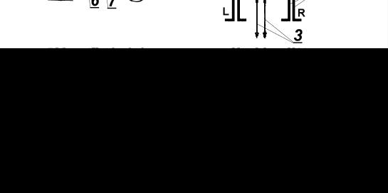
Schematic showing the set-up of the pedals controlling the rudder
1.Rudder pedals
2.Cable pulley
3.Cables
4.Rudder lever
5.Rudder
6.Tension springs
7.Discharge cables
Page 7-10 |
SEPTEMBER, 2004 |
|
AEROPLANE FLIGHT MANUAL |