

AT-3 R100 POH
.pdf“AERO” Sp. z o.o. |
SECTION 7 |
AT-3 R100 |
DESCRIPTION OF THE AEROPLANE |
|
AND ITS EQUIPMENT |
7.7. Luggage compartment |
|
The luggage compartment is located behind the seats and consists of two containers (see illustration).
The containers are fitted with lids made of metal, locked by latches. Pressing the latch releases it and enables the lid to be opened. The luggage compartment allows for luggage of 30 kg total weight; 20 kg in the port container and 10 kg in the starboard one.
Lid of the luggage compartment
The port and the starboard luggage containers
Extinguisher
CAUTION
IT IS PROHIBITED TO CARRY INFLAMMABLE, CORROSIVE, EXPLOSIVE, RADIOACTIVE AND OTHER MATERIALS IN THE LUGGAGE COMPARTMENT, WHICH ARE HARMFUL FOR HUMAN HEALTH OR LIFE.
JULY, 2010 |
9 |
|
Page 7-21 |
|
AEROPLANE FLIGHT MANUAL |
|
|
|
|
SECTION 7 |
“AERO” Sp. z o.o. |
DESCRIPTION OF THE AEROPLANE |
AT-3 R100 |
AND ITS EQUIPMENT |
|
7.8. Canopy |
|
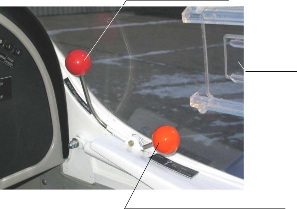
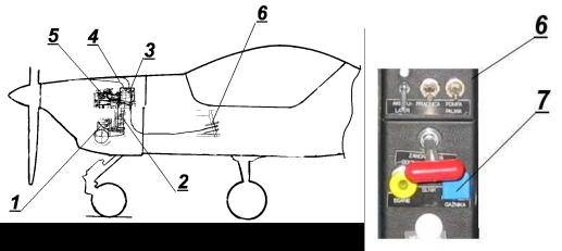
The canopy consists of an epoxy fibreglass composite frame and of profiled acrylic sheet. The canopy can be moved forward, rotating around an axis located in front of the cabin. After entering the cabin the canopy should be pulled on the handle and lowered, until it rests on the fuselage sidewall edges, and then locked with the levers with orange knobs. Sliding venting tabs are installed on both sides of the canopy. Jettisoning of the canopy is achieved by pulling the lever with the red knob and pushing the canopy upwards. The locking and the jettisoning levers are arranged in the front part of the canopy on both sides, one of each, on each side.
Canopy jettisoning lever
Air deflecting
tab
Lever locking and opening the canopy
Page 7-22 |
9 |
JULY, 2010 |
|
|
AEROPLANE FLIGHT MANUAL |
|
|
“AERO” Sp. z o.o. |
SECTION 7 |
AT-3 R100 |
DESCRIPTION OF THE AEROPLANE |
|
AND ITS EQUIPMENT |
7.9. Power unit |
|
7.9.1. Engine
Rotax 912S2 or 912S4 engine
-Four-stroke, opposed, four cylinder engine
-Cylinder heads cooled with fluid, cylinders cooled with air
-Pressure lubrication
-Dual magneto ignition
-Propeller driven via reduction gear
-Electric starter
-Generator
Two interconnected throttle levers, located on the instrument panel, are used to control the engine.
7.9.2. Propeller
Wooden, fixed pitch, two-bladed GT-2/173/VRR-FW101SRTC, propeller, of 1.73 m (5’ 8’’) diameter.
The propeller rotates in a clockwise direction (when viewed from the cockpit)
JULY, 2010 |
9 |
|
Page 7-23 |
|
AEROPLANE FLIGHT MANUAL |
|
|
|
|
SECTION 7 |
“AERO” Sp. z o.o. |
DESCRIPTION OF THE AEROPLANE |
AT-3 R100 |
AND ITS EQUIPMENT |
|
7.10. Fuel system |
|
The fuel is contained in the fuel tank, which is located between the instrument panel and the firewall. The fuel tank, made of composite, is contained in a sack, made of fabric resistant to smoke and to fuel.
There are drains installed in the sack, to drain any spilled fuel out of the aeroplane. The fuel tank is fitted with a filler which is drained. A measuring stick is attached to the filler cap. The fuel quantity is measured by the fuel level sensor. The signal from this sensor is transmitted to the fuel quantity indicator and to the reserve fuel sensor. The reserve fuel signal lamp starts to light, when the fuel tank contains 10 litres of consumable fuel.
The fuel is filtered by the coarse filter located on the fuel tank outlet, by the filter in the electric driven emergency fuel pump and by the fine filter, located behind the engine driven pump.
The fuel shut-off valve is located under the fuel tank, behind the firewall, and is operated from the cabin.
The engine driven pump feeds the fuel under pressure via a five-way connector to the carburettors and to the fuel pressure sensor. Surplus fuel is drained back to the fuel tank.
Page 7-24 |
9 |
JULY, 2010 |
|
|
AEROPLANE FLIGHT MANUAL |
|
|
“AERO” Sp. z o.o. |
SECTION 7 |
AT-3 R100 |
DESCRIPTION OF THE AEROPLANE |
|
AND ITS EQUIPMENT |
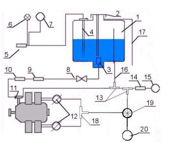
Diagram of the fuel system
1.Fuel tank
2.Filler cap with the measuring stick
3.Coarse fuel filter
4.Fuel level sensor
5.Reserve fuel sensor
6.Reserve fuel signalling lamp
7.Fuel quantity indicator
8.Shut-off valve
9.Electrically driven fuel pump
10.Fine fuel filter
11.Engine driven fuel pump
12.Carburettors
13.Three-way connectors
14.Fuel pressure sensor
15.Fuel pressure indicator
16.Fuel return line
17.Draining line of fuel filler
18.Three-way connectors
19.Fuel flow-meter sensor (optional)
20.Fuel flow-meter indicator (optional)
JULY, 2010 |
9 |
Page 7-25 |
|
AEROPLANE FLIGHT MANUAL |
|
SECTION 7 |
“AERO” Sp. z o.o. |
DESCRIPTION OF THE AEROPLANE |
AT-3 R100 |
AND ITS EQUIPMENT |
|
7.11. Pitot and static pressure systems |
|
The sensors [9] and [8] receive air under pitot and static pressure and transmit it to the airspeed indicator [3], altimeter [2] , vertical speed indicator [1] and altitude encoder[7](option) -see the scheme on the illustration. The sensors of pitot and static pressure are fixed under the port wing. Water sediment containers [6] are installed to both the static pressure line [5] and to the pitot pressure line [4]. The sediment containers are located beneath the pilot’s seat and are accessible from outside.
Page 7-26 |
9 |
JULY, 2010 |
|
|
AEROPLANE FLIGHT MANUAL |
|
|
“AERO” Sp. z o.o. |
SECTION 7 |
AT-3 R100 |
DESCRIPTION OF THE AEROPLANE |
|
AND ITS EQUIPMENT |
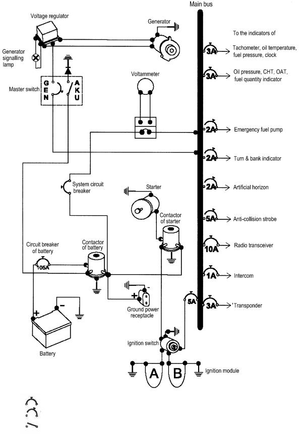
7.12. Electrical system |
|
The source of on board electric power is the generator and the battery. It is a 12 Volt system. Automatic circuit breakers located on the instrument panel protect the system. The BATTERY switch switches on the system. The switches BATTERY and GENERATOR perform the task of the system master switch. In case of generator failure, the GENERATOR signalling lamp lights up. In such a case the system is fed from the on board battery.
There is also an electrical ground power receptacle installed into the system, being located in front of the wing, on the port wall of the fuselage, in front of the firewall. An electric board socked is installed in the cabin, on the instrument panel. When using the ground power source, the on board battery is automatically switched off. Switching of the electric power receivers in this case is the same as when using the on board battery.
The following options are available:
-Anti-collision strobe
-Navigation lights and the landing light
JULY, 2010 |
9 |
Page 7-27 |
|
AEROPLANE FLIGHT MANUAL |
|
SECTION 7 |
“AERO” Sp. z o.o. |
DESCRIPTION OF THE AEROPLANE |
AT-3 R100 |
AND ITS EQUIPMENT |
|
Automatic circuit breaker (permanently switched on)
Switch with automatic circuit breaker (switched manually)
Switch (switched manually)
Page 7-28 |
9 |
JULY, 2010 |
|
|
AEROPLANE FLIGHT MANUAL |
|
|

“AERO” Sp. z o.o. |
SECTION 7 |
AT-3 R100 |
DESCRIPTION OF THE AEROPLANE |
|
AND ITS EQUIPMENT |
7.13. Aeroplane equipment |
|
A detailed list of standard aeroplane equipment, as well as of the possible optional equipment is given in the Maintenance Manual of the AT-3 R100 aeroplane. The operational instructions for the optional equipment are given in the section 9 – Supplements.
7.13.1. Cabin ventilation and heating
The cold air ventilation inlet in the lower part of the cabin shares the air intake with the carburettor air inlet connected to the air mixer. The air mixer enables adjustment of the volume and temperature of the cabin ventilating air. The fresh air is ducted from the intake to the heat exchanger located under the muffler and then further to the air mixer. From the mixer the air is ducted to the cabin outlet. The control cables and knobs are located on the middle console.
1. |
Cold air inlet |
7. |
Muffler |
|||
2. |
Heat exchanger inlet |
8. |
Heat exchanger intake - optional |
|||
3. |
Heat exchanger |
9. |
Control cables |
|||
4. |
Mixer |
10. |
Temperature control knob |
|||
5. |
Cabin inlet |
11. |
Air volume control knob |
|||
6. |
Middle console |
|
|
|
|
|
|
|
|
|
|||
JULY, 2010 |
|
|
9 |
|
Page 7-29 |
|
|
AEROPLANE FLIGHT MANUAL |
|
|
|||
|
|
|||||
SECTION 7 |
“AERO” Sp. z o.o. |
DESCRIPTION OF THE AEROPLANE |
AT-3 R100 |
AND ITS EQUIPMENT |
|
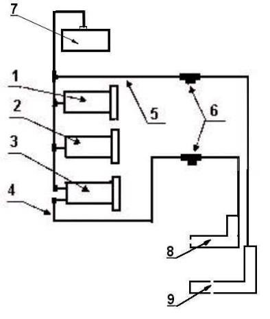
7.13.2. Carburettor heating installation |
|
Closing of the air flow from the cold air inlet causes suction of the hot air from the engine compartment through the heat exchanger located above the muffler. The heated air is channelled through the air duct to the filter box, where the air streams are mixed. The cold air stream can be adjusted by the flap controlled by the Bowden cable and knob located on the middle console. The temperature of the carburettor intake air can be read from the gauge on the instrument panel.
To increase of the temperature turn the knob to the left to unlock and pull to the selected position and turn right to lock.
1.Heat exchanger
2.Duct
3.Air filter box
4.Air intake
5.Carburettors
6.Middle console
7.Carburettor heating control knob
Page 7-30 |
9 |
JULY, 2010 |
|
|
AEROPLANE FLIGHT MANUAL |
|
|