

AT-3 R100 POH
.pdf“AERO” Sp. z o.o. |
SECTION 7 |
AT-3 R100 |
DESCRIPTION OF THE AEROPLANE |
|
AND ITS EQUIPMENT |
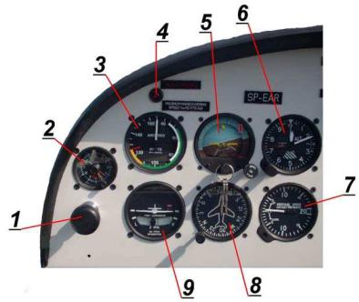
7.4. Instrument panel
The equipment installed in this
aeroplane is specified in the List
of Equipment on page 6-4.
SEPTEMBER, 2004 |
Page 7-11 |
AEROPLANE FLIGHT MANUAL |
|
SECTION 7 |
“AERO” Sp. z o.o. |
DESCRIPTION OF THE AEROPLANE |
AT-3 R100 |
AND ITS EQUIPMENT |
|
1- Port throttle lever
2- Clock *
3- Airspeed indicator
4- Stall warning light *
5- Artificial horizon *
6- Altimeter
7- Vertical speed indicator
8- Directional gyro *
9- Turn co-ordinator *
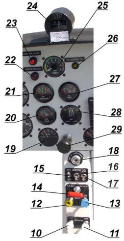
10Cabin heating control knob
11Vent control knob
12Choke
13Carburettor heating
14Fuel cut-off valve
15Battery switch
16Generator |
switch |
17Fuel pump switch |
|
18Ignition switch |
|
Page 7-12 |
SEPTEMBER, 2004 |
AEROPLANE FLIGHT MANUAL
“AERO” Sp. z o.o. |
SECTION 7 |
AT-3 R100 |
DESCRIPTION OF THE AEROPLANE |
|
AND ITS EQUIPMENT |
19-Fuel quantity indicator
20-Cylinder head temperature indicator (CHT)
21-Oil pressure indicator
22-“Starter engaged” light
23-“Generator failure” light
24Compass
25Tachometer
26- “Fuel reserve” light
27Oil temperature indicator
28-Exhaust Gas temperature indicator (EGT)
29-Throttle lever
SEPTEMBER, 2004 |
Page 7-13 |
AEROPLANE FLIGHT MANUAL |
|

SECTION 7 |
“AERO” Sp. z o.o. |
DESCRIPTION OF THE AEROPLANE |
AT-3 R100 |
AND ITS EQUIPMENT |
|
30-Volt-Ammeter
31-Hour meter *
32Carburettor air temperature indicator
33Fuel pressure indicator
34Transponder *
35- Radio-transceiver *
3612V- DC Supply
37Intercom *
38- Anti-collision strobe light switch
39Turn co-ordinator switch
40Artificial horizon – switch
41Directional gyro – switch *
42Starter – circuit breaker
43Engine instruments - circuit breaker
44-Fuel quantity meter - circuit breaker 45- 12V-DC-supply - circuit breaker 46- ”Encoder” - circuit breaker *
47Transponder - circuit breaker *
48Intercom - circuit breaker *
49- Radio-transceiver- circuit breaker * * - optional equipment
Page 7-14 |
SEPTEMBER, 2004 |
|
AEROPLANE FLIGHT MANUAL |

“AERO” Sp. z o.o. |
SECTION 7 |
AT-3 R100 |
DESCRIPTION OF THE AEROPLANE |
|
AND ITS EQUIPMENT |
7.5. Landing gear system |
|
The aircraft has a three-wheel, fixed landing gear, with nose wheel. The main landing gear is of a flat spring design. The nose wheel is fitted with a rubber shock absorber
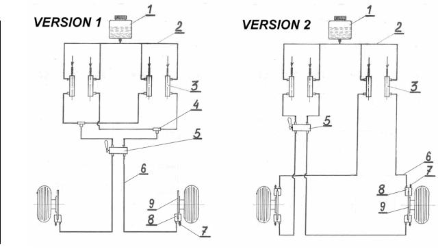
7.5.1. Braking system
The aeroplane is fitted with hydraulic disc brakes. The system consists of two hydraulic circuits that activate independent callipers of left and right wheels of the main landing gear. Each of the circuits consists of two brake cylinders [3] located on rudder pedals. In version 1 they are connected via insulating valve [4] and flexible pressure lines with brake callipers [8]. The brake fluid container [1] is located at the highest point of the brake system on the firewall and it supplies each pump independently. Cylinders of the left brake are activated by the left rudder pedals and the right cylinders are activated by the right rudder pedals of both the pilot and the passenger. The insulating valve are located on the firewall in the cabin and prevent the transfer of brake fluid under high pressure from one cylinder to the other instead of the callipers. In version 2 pumps on right rudder pedals activate additional callipers.
In both variations it is possible to install a parking brake valve.
9
9
JULY, 2010 |
Page 7-15 |
|
AEROPLANE FLIGHT MANUAL |
SECTION 7 |
“AERO” Sp. z o.o. |
DESCRIPTION OF THE AEROPLANE |
AT-3 R100 |
AND ITS EQUIPMENT |
|
9
Diagram of the braking system
1 Brake fluid container
2 Feeding line
3 Brake cylinder
4Insulating valve
5 Parking brake valve (option)
6 Brake pressure line
7 Bleeding valve
8 Brake calliper
9Brake disk
Page 7-16 |
JULY, 2010 |
|
AEROPLANE FLIGHT MANUAL |
“AERO” Sp. z o.o. |
SECTION 7 |
AT-3 R100 |
DESCRIPTION OF THE AEROPLANE |
|
AND ITS EQUIPMENT |
7.5.2. Parking Brake
The parking brake valve is installed in between the seats tunnel and
the parking brake lever is accessible from the left seat.
CAUTION
ENGINE STARTING WITH PARKING BRAKE ON IS PROHIBITED
NOTE
IN ORDER TO APPLY THE PARKING BRAKE IT IS NECESSARY:
-FROM THE LEFT SEAT PUSH ON TOE BRAKES
-ROTATE PARKING VALVE LEVER TO POSITION “ON”
NOTE
DUE TO POSSIBLE DECREASE IN PRESSURE IN THE BRAKE LINES OVER A LONGER PERIOD OF PARKING TIME IT IS
RECOMMENDED TO FURTHER SECURE THE AIRPLANE AS A 9
PREVENTIVE MEASURE FROM ROLLING.
The parking valve can occur in two types. Type of installed parking brake is specified in Section 6 of this manual, see table “Optional equipment”.
For parking brake variant 2 the valve is installed in break installation of left seat.
For role of the parking brake and the flight controls securing can be used the collapsible tow bar installed on control stick and rudder control pedals. For collapsible tow bar using description see Section 8.4.2 „Parking”.
JULY, 2010 |
Page 7-17 |
|
AEROPLANE FLIGHT MANUAL |
SECTION 7 |
“AERO” Sp. z o.o. |
DESCRIPTION OF THE AEROPLANE |
AT-3 R100 |
AND ITS EQUIPMENT |
|
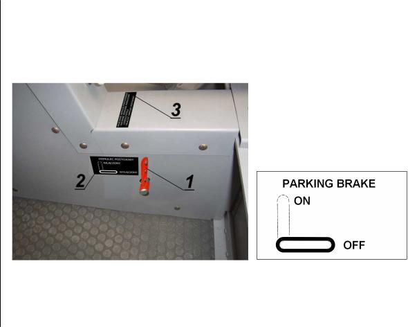
Parking Brake AT3.47.100.0
Valve of parking brake AT3.47.100.0 is non-return valve. After set this valve lever “on” is possible to increase pressure inside the breaking system lines and brake the airplane.
9
Parking brake AT3.47.100.0 in „ON” position
1.Valve lever,
2.Parking brake placard,
3.Information placard,
Page 7-18 |
JULY, 2010 |
|
AEROPLANE FLIGHT MANUAL |
“AERO” Sp. z o.o. |
SECTION 7 |
AT-3 R100 |
DESCRIPTION OF THE AEROPLANE |
|
AND ITS EQUIPMENT |
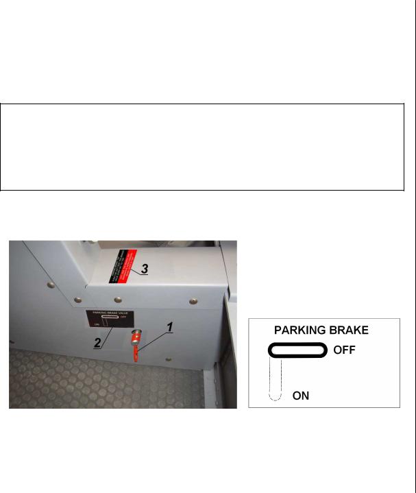
Parking Brake AT3.47.130.0
Valve of parking brake AT3.47.130.0 is cut-off valve. After set this valve lever “on” is not possible to increase pressure inside the breaking system lines, brake cylinders are cut off from callipers. Set the valve lever to position “on” with low level pressure inside the braking lines make impossible to brake the airplane.
CAUTION
DO NOT APPLY PARKING BRAKE BEFORE PUSH ON
BRAKE LEVERS
LEFT SEAT BRAKES DO NOT OPERATE WHEN
PARKING BRAKE IS ON
In airplane with brake system variant 2 right seat toe brakes operate independently from parking brake lever position.
9
Parking brake AT3.47.130.0 in „ON” position
1.Valve lever,
2.Parking brake placard,
3.Information placard,
JULY, 2010 |
Page 7-19 |
|
AEROPLANE FLIGHT MANUAL |
SECTION 7 |
“AERO” Sp. z o.o. |
DESCRIPTION OF THE AEROPLANE |
AT-3 R100 |
AND ITS EQUIPMENT |
|
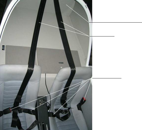
7.6. Seats, seat belts and harness
The seat position is permanently fixed (not adjustable). The illustration below shows the installation of the seats. Each seat is fitted with adjustable safety belts.
Rear frame of fuselage
Harness
Safety belts
Page 7-20 |
9 |
JULY, 2010 |
|
|
AEROPLANE FLIGHT MANUAL |