

Sec. 19. Reference of Maps and Plans
The system of lettering and numbering map sheets is the reference of a map. To facilitate the use of a map consisting of many sheets the convention is to give each map sheet its own designation. The arrangement of the map sheets is indicated in what is called a reference sheet.
The basis for a reference of maps of different scales in the Soviet Union is provided by the National Million Map or the International Map of the World (1/1 000 000).
The sheets of this map are arranged as follows. The entire surface of the globe is divided into rows or belts with parallels spaced at
Fig. 20
intervals of 4° of latitude from the Equator and into columns with meridians drawn at intervals of 6° of longitude. Thus 60 columns are obtained. The rows are designated by Latin capital letters from the Equator to the North and South poles. The columns are numbered with Arabic numerals west to east and starting from the 180° meridian (Fig. 20). The sheets of a 10-km map are thus bounded by the meridians and parallels that form the columns and rows (1/1 000 000). The margins of each map sheet form an isosceles trapezoid.
Each sheet of the 10-km map of the USSR, covers 4° of latitude and 6° of longitude. In northern latitudes from 60 to 76° each map sheet covers twice as much longitude, and from 70 to 88° four times as much.
Sec. 80. Methods of Levelling
Direct (geometrical) levelling is done using a horizontal ray of light. The intent of this type of levelling is to find height differences between a number of points. Given the height of ah initial point and the height differences (vertical distances) of the other points with respect to
Fig. 106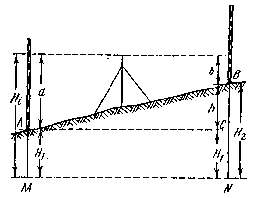
the first, it is possible to ascertain the elevations of all the other points on the ground. The height differences also called relative elevations or differences in level are obtained from direct levelling by the reading on a levelling staff (rod) where the horizontal line of sight of the geodetic (surveyor's) level strikes. There are two sorts of levelling: by the two staff technique and levelling forward.
Direct levelling by the two staff technique. In order to ascertain the height difference of a point B relative to a point A (Fig. 106), hold two levelling staffs (graduated in centimeters) vertically, one at A, the other at B. Set up the geodetic level roughly equidistant between the two points. Pointing the horizontal line of sight of the instrument successively at the two staffs, take readings from each, a and b. As can be seen from Fig. 106, the vertical distance h which we want is determined by the equation
h = a – b (15.1)
If convenient, assume A is the back point and B is the forward point, then we may say that the height difference of the forward point relative to the back point is equal to a sight (staff reading) backwards minus the sight forwards.
If the height difference, as found by the above formula, is positive, then the forward point is higher than the back point. Consequently, the line AB rises. A negative height difference would mean that B is below A, that is, the line AB falls.
Knowing the height H2 of A and the height difference of B relative to A, we can find the height H2 of B from the formula
H2 = H1 + h (15.2)
that is, the height of the next point is equal to the height of the previous point plus the appropriate height difference.
The height of the line of sight above mean sea level (the datum surface) or above some assumed datum is said to be the height of the instrument (HI). As can be seen from Fig. 106, the height of the instrument is
Hi = H1 + a (15.3)
that is, the height of the instrument is equal to the point's height plus the sight (staff reading) of this point.
Knowing the height of the instrument, we can easily find the height of any point to which a sight has been made a foresight*(* A foresight (F.S.) and a backsight (B.S.) are the terms extensively used by American and British surveyors. The point whose height is known is called a backsight, or plus sight. The point whose height is to be determined is termed a foresight, or minus sight.—(Translator's note)). It can be seen from Fig. 106 that
H2 = H1 – b (15.4)
that is, a point's height is equal to the height of the instrument minus the sight at this point.
Thus, it is possible to ascertain using two methods the height of a point, given the height of one point and the sight at it and at the other points. The first method uses height differences, the other the height of the instrument. One method can serve as a check on the other.
It is best to calculate point heights from the height of the instrument when sights are taken of a few points from one instrument station and the height of one of the points is known.
Levelling forward. A geodetic level happens sometimes to be set up with its telescope's ocular lens plumb true above the point A (Fig. 107). The vertical distance i from the ocular's
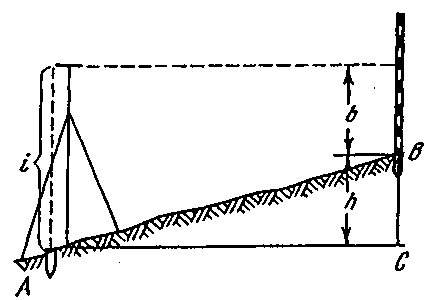
centre to point A, the telescope's line of sight (its optical axis) being true level, is said to be the instrument's altitude.
Let a staff be set up over a point B. By pointing a horizontal line of sight at it and taking a staff reading b, we obtain
h = i – b (15.5)
that is, the height difference is equal to the instrument's altitude minus the sight forward. The instrument's altitude Fig. 107 can be measured using a graduated staff or a ribbon tape. If the forward point B is above the back point A, the height difference will be positive. If the slope from A to B is downward, then the height difference will be negative.