

1.2. Electromagnets with external forward armature travel
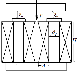
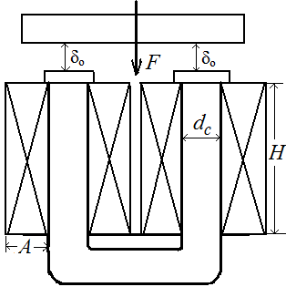
The most widespread forms of electromagnets of this type are electromagnets, presented on fig 1.3. As it follows from pictures, in examined cases there are two identical basic air-gap, in this connection a full electromagnetic force F is determined by a formula
F = 2F0 = 2∙5,1∙B02∙ S0 / μ0,
Fig. 1.3, a where В0 − induction in a basic air-gap, Wb/сm2; S0 − equivalence cross-section of each of basic gaps, сm2.
So, MMF, being on both gaps, determined so:
(w∙I)0 = φ (w∙I)П = 2∙δ0∙B0 / μ0,
where φ − coefficient, taking into account of MMF drop in steel and non-working gaps.
 Induction
В0
with a
glance of
possible in
exploitation lowering of
MMF
(w∙I)п
=
χ∙w∙I,
where χ ≤ 1, equals
to:
B0
= μ0∙φ∙χ∙w∙I
/ 2δ0
Induction
В0
with a
glance of
possible in
exploitation lowering of
MMF
(w∙I)п
=
χ∙w∙I,
where χ ≤ 1, equals
to:
B0
= μ0∙φ∙χ∙w∙I
/ 2δ0
Permissible MMF w∙I of electromagnet coils is determined coming from its operation mode, terms of heating and presence of two coils, having a cooling surface 2Scl.
a) Continuous running duty of Fig. 1.3, b electromagnet
For this mode next correlations, similar to got before, are correct. Resistance of one coil :
R = 10-4∙ρ∙π∙(1 + n)∙dc∙w / 2Sm
where w − total number of loops of both coils; Sm – cross-section of wire metal, equals to :
Sm = 2fap∙m∙n∙ dc2 / w.
So, general losses in resistance of electromagnet are equal to:
P = 2R∙I2 = 10-4∙ρ∙π∙(1 + n)∙w2∙I2 / fap∙m∙n∙dc
On the other hand, Р is determined from correlation
Θper = P / 2h∙Scl = P / [2h∙(Sex + α∙Sin)].
Substituted Р and Scl from (1.5) into the formula Θper, we will define the value of MMF of electromagnet:
w∙I = 2√[104∙fap∙m2∙n∙(1 + 2n + α)∙h∙Θper∙dc3 / ρ(1 + n)]
the value of electromagnetic force
F = 8∙104∙μ0∙φ2∙ε2∙χ2∙fap ∙τ2∙m2∙n∙(1+ 2n + α)∙h∙Θper∙dc5/ [ρ(1 + n) δ02],
and key size of a core
dс = 5√{[103∙ρ∙(1 + n)∙F∙δ02 / [φ2∙ε2∙χ2∙fap∙τ2∙m2∙n∙(1+ 2n + α)∙h∙Θper]}
Designating, as well as before,
C1 = [2∙103∙ρ(1+n)] / [φ2∙χ2∙fap∙τ2∙m2∙n∙(1+2n+α)∙h∙Θper], we will get accordingly:
F = 2ε2∙dc5 / (C1∙ δ02) (1.42)
and dc = 5√[C1∙F∙δ02 / 2ε2] (1.43)
Transformation of the last formula gives dependence
F / δ03 = 2ε2∙χ5 / C1, (1.44)
facilitating, as it was explained before, determination of dc = χ∙δ0. Thus under F they understand full force of electromagnet. In this case we determine:
MMF of coils
w∙I = (9∙103∙dc / φ∙χ∙τ)∙√(dc / C1) (1.45)
2) cross-section of wire
Sm = [2.82∙ρ∙(1 + n)∙dc2 / (φ∙χ∙τ∙U)]∙√(dc / C1) (1.46)
3) number of coil loops
w = U∙√[103∙fap∙n / ρ∙(1 + n)∙(1 + 2n + α)∙h∙Θper∙dc) ] = C2∙U∙√(C1 /dc) (1.47)
4) induction in a working air-gap
B0 = (0,396∙10-4√F) / (τ∙ε∙dc)
approximately by a formula
B0 ≈ (4∙10-5 / τ∙ 5√C1) ∙√(F3/ δ04)