

4. Active and inductive resistances of stator and rotor winding
Calculation of active resistances. Activee resistance of phase of stator winding is calculated, according to a formula (2.3). Resistance r1 is in the heated state
r1 = r1ϑ = r1 200 [1 + 0,004(ϑ + ϑenv − 20°)], (25)
where r1 200 = (wph1∙lar av) / (57Sar∙a1∙a2) − resistance of stator phase at 20°C, Ω; ϑ − the expected overheat of winding, °C; ϑenv − temperature of environment; lar av − average length of loop of armature winding, m.
Active resistance of phase of squirrel-cage rotor in the heated state is (fig. 4.9)
r2 = r2ϑ = (1/p)(rb + rr) [1 + α∙(ϑ + ϑenv − 20°)], (26)
where р − number of poles pair; rb − active resistance of rotor bar (at 20° С); rr − active resistance of s.c. rings (at 20° С); α − temperature coefficient of material resistance of rotor winding.
Active resistance of rotor bar
rb200 = (lb / Sb)∙ρ, (27)
where lb − length of rotor bar, m; Sb – cross-section area of bar, mm2; ρ − specific electric resistance of bar material at 20° С.
For rotors with an aluminium pouring for a slot, represented on a fig. 4.9, c, the area of cross-section of bar is determined by a formula (mm2)
Sb = π(b1 − 0,2)2 / 8 + π(b2 − 0,2)2 / 8 + (b1 + b2 − 0,4)∙h1 / 2 (28) Active resistance of s.c. rings, reduced to the bar (at 20° С),
rr20о = 2π∙Dr / [z2∙Sr∙(2sin π∙p/z2)2]∙ρ, (29)
where Dr − diameter of s.c. ring, m; Sr − area of cross-section of s.c. ring, mm2.
Active resistance of phase of rotor winding, resulted to the stator winding,
r'2 = r2∙krd, (30)
where krd − coefficient of reduction;
krd = (m1/m2) [wph1∙kw1 / (wph2∙ kw2)]2 = 4p∙m1∙wph12kw12 /z2 (31)
At m1 = 3
krd = w2ph1∙k2w1 / (w2ph2∙ k2w2) = 12∙p∙ w2ph1∙k2w1 / z2. (32)
Values of specific resistances ρ and temperature coefficients α for materials, applied for shortcircuited windings, driven to the table.7.
Tabl. 7
Material |
ρ, Ω∙ mm2/m |
α |
γ |
Copper M-1 |
0,0175=1/57 |
0,0040 |
8,9 |
Brass ЛС-59-1 |
0,065 |
0,0026 |
8,5 |
Brass Л-62 |
0,071 |
0,0017 |
8,5 |
Aluminium |
0,035=2/57* |
− |
2,6 |
* For an aluminium a value ρ takes into account the presence of emptinesses at pouring.
Calculation of inductive resistances. Inductive resistance of stator winding phase (Ω)
Xs1 = [4π∙f1∙w2ph1∙l1 / (p∙q1)] ∑λ1∙10-8 (33)
where q1 = z1/ (2p∙m1) – a number of slots on a pole and phase of stator winding; l1 − active length of stator; f − frequency of network; λ1 − total specific conductivity for the leakage fluxes of stator winding.
Inductive resistance of phase of shortcircuited rotor
Xs2 = (2π∙f1∙l2 /p)∙∑λ2∙10-8 (34)
where l2 − active length of rotor; ∑λ2 − total specific conductivity for the leakage fluxes of rotor
∑λ2 = λsl2 + λδ2 + λec2 (35)
where λsl2 − specific conductivity of slot dispersion of rotor; λδ2 − specific conductivity of dissipation in an air-gap; λec2 − specific conductivity of dissipation of end coils.
Specific conductivity of rotor slot dissipation λsl2 equals to:
а) for a round slot (fig. 9, а)
λsl2 = 1,25(0,66 + hlm2 / bg2); (36)
b) for a pyriform slot (fig. 9, b)
λsl2 = 1,25 [(2/3)∙h1/ (b1 + b2) + 0,66 + hlm2 / bg2]; (37)
c) for pyriform closed slot (fig. 9, c)
λsl2 = 1,25 [(2/3)∙h1/ (b1 + b2) + λsb],
where λsb − specific conductivity of leakage fluxes through the bridge of slot, determined graphicaly.
Specific conductivity of dissipation in an air-gap λδ2 for motors with a shortcircuited rotor
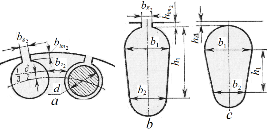
Fig. 9
For motors of very small power with a shortcircuited rotor a specific conductivity A,к2 can be count up by a formula
λδ2 = (tz1 – bg1 − bg2) / (12,8∙δ), (39)
where bg1 and bg2 − width of stator and rotor slot slit respectively.
Specific conductivity of dissipation of end coils of s.c. rotor
λec2 = 2,89Dr / [z2∙l2∙(2sin πρ / z2)2]∙lg2,36 Dr av / (a + b), (40)
where Dr av − average diameter of s.c. ring; (a + b) − half of perimeter of section of s.c. ring.
Inductive resistance of winding phase of s.c. rotor, reduced to the stator winding,
X ‘s2 = Xs2∙krd = Xs2(4p∙m1∙wph12∙kw12) / z2 (41)