

Lecture 2.4
THEME 2.2: REGIONAL/RANG AIRPLANE ENGINE SYSTEMS ELECTRICAL EQUIPMENT
The aircraft engine is installed with many systems requiring electrical power. The predominant requirement (in terms of current consumption) is for the starting system. General aviation aircraft use electrical starter motors for both piston and gas turbine engines; larger transport aircraft use an air-start system (controlled electrically) derived from ground support equipment or by air cross-fed from another engine. Electrical starting systems on piston and gas turbine engines are very different. The trend towards the all-electric aircraft will see more aircraft types using electrical starting methods. The engine also requires electrical power for the ignition system. Once again, the needs of piston and gas turbine engines are quite different. Although starting and ignition systems are described in this chapter as separate systems, they are both required on a co-ordinated basis, i.e. a means to rotate the engine and ignite the air/fuel mixture.
Electrical and electronic requirements for engines also include the variety of indicating systems required to operate and manage the engine. These indicating systems include (but are not limited to) the measurement and indication of: rotational speed, thrust, torque, temperature, fuel flow and oil pressure. Indications can be provided by individual indicators or by electronic displays. This theme describes engine starting, ignition and indicating system for both piston and gas turbine engines.
2.2.1. Airplane fuel quantity and engine/apu oil systems electrical equipment
2.2.1.1. Engine Fuel
Engine fuel system indicators generally consists of fuel flow and temperature.
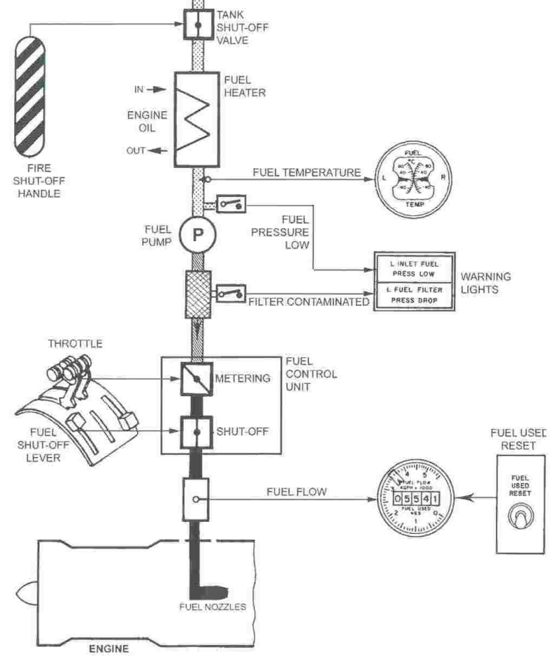
Figure: Engine Fuel System
Many cockpits include warning lights for low fuel pressure and for filter bypass if contaminated.
Fuel Temperature
Fuel Temperature - receives signal from a temperature sensor located at the fuel heater output line.
Fuel Flow
FF Gauge - receives signal from a fuel flow transmitter located in the fuel control metered line to the combustor.
Warning Lights
INLET FUEL PRESSURE LOW:
Indicate fuel supply pressure to engine is to low.
FUEL FILTER PRESS DROP:
Indicate fuel filter differential pressure is high due of ice or contamination.
Fuel Used Reset
Resets fuel used digital counter to zero. 00000
Fuel Flow Indicating System
The fuel flow indication system for turbine engines measures fuel consumption in pounds or kilogram per hour. The fuel flow meter measure mass flow rather than volume. In this way, it compensates for fuel temperature in its read-out.
Types of fuel flow meter are in use:
Vane type
Synchronous motor type
Motor less mass flow meter.
Vane-Type Flow Meter
The vane type is designed to measure volume of flow. The system consists of a flow meter transmitter generally located in the engine fuel line to the combustor and an indicator located in the cockpit.
The synchros of both the transmitter and indicator, connected in parallel and are excited with 26V, 400 Hz. As the vane is moved against its restraining spring by volume of flow, the transmitter rotor moves along with the vane. The rotor in the indicator tracks along with the transmitter magnet, giving a fuel flow reading to the pilot. The gauge in the illustration indicates in pounds per hour.
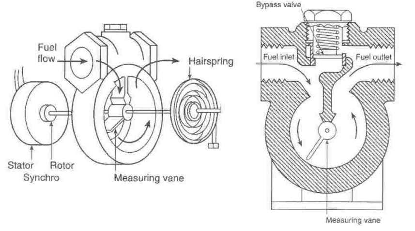
Figure : Vane type fuel flow transmitter

Figure: Vane type fuel flow indicating system schematic
Synchronous Mass Flow
This system, more recently developed than the vane type, is said to have greater accuracy in that it measures mass flow rather than volume. In this way, it compensates for fuel temperature in its read-out.
The system in measures in kilogramm or pounds per hour. Fuel enters the transmitter impeller, which is rotated at a constant 60 revolutions per minute by the synchronous impeller motor. The temperature of the fuel will determine its volume and the amount of force to be created by the action of the impeller.
The turbine is twisted against its restraining spring by the mass flow force created by impeller movement. The mass flow electrical transmitter arrangement is similar to the vane type system.
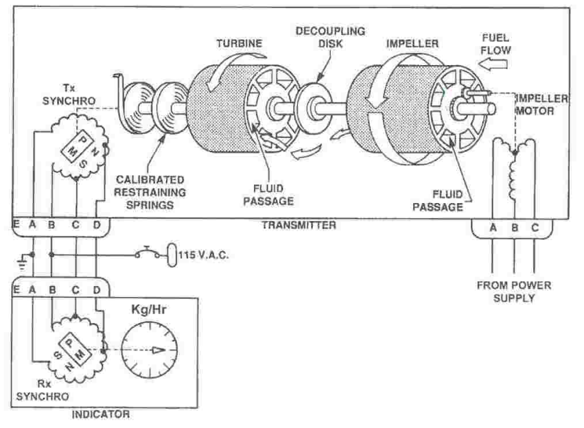
Figure: Fuel flow indicating system

Figure: Fuel Flow Indicating System Example
Motorless Mass Flow Meter
The motor less flow meter represents the latest in electronic solid-state fuel measuring systems. It is small in size and accounts for variables such as fuel temperatures and specific gravity with an accuracy of 1% as opposed to approximately 2% for motor driven flow meters. Almost all of the large turbine powered aircraft are configured with the motorise type, kilogramm or pound per hour fuel flow meter system. The read out is on a digital display rather than the traditional gauge and pointer.
The flow meter transmitter converts flow rate into two electronic signals. The signals are created as the flowing fuel gives an angular displacement to two continuously rotating magnets. The magnets induce electronic impulses into stationary coils and the time difference between pulses 1 and 2 is used as a measure of mass flow rate.
The fuel enters from the drive end and rotates the drum containing Magnet No. 1 and the drive shaft. The spring connects the drive shaft to the impeller containing Magnet No. 2. As the magnets rotate, the pickoff coils receive current pulses, the first pulse occurring at Pick-off Coil No. 1. Then as the spring deflects in proportion to fuel flow, No. 2 magnet turns with the impeller and induces a current pulse with a time lag into Pick-off Coil No. 2.
The greater the mass flow, the greater the spring deflection and angular difference between the magnets. The time displacement which results is directly proportional to mass flow rate in this motorless transmitter design.
The cockpit indicator contains electronics which convert the time difference to a mass per hour (kg/hr or Ibs/hr) readout.
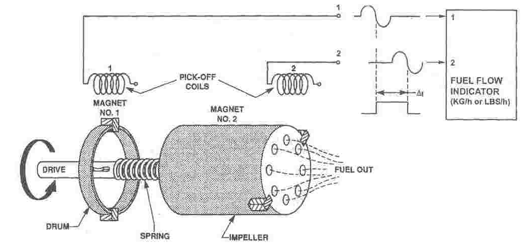
Figure: Motorless Fuel Flow Meter
Fuel Flow Indication System
A fuel flow transmitter is in the fuel line between the fuel filter and the HP fuel pump. The fuel flow transmitter is a motorless, turbine driven type.
The transmitter converts the fuel flow rate to the engine into an electrical signal The mass of the fuel flow creates an angular displacement between two rotating magnets. Each revolution the magnets induce a pulse in their stationary pick-up coil. The angular displacement results in a time delay between the two output pulses.
The fuel flow enters the transmitter and drives the turbine at a constant speed of 300 RPM. The turbine drives the drum through the common drive shaft. The stationary flow straightener ensures a laminar flow through the transmitter. A spring between the drive shaft and the impeller allows displacement when the mass of the fuel flow passes the impeller. The angular displacement is proportional to the fuel flow rate. A jammed rotor has no effect on engine performance, because the pressure drop across the transmitter is minimal.
A pulse shaper in the EMUX (Engine Multiplexer) conditions the signal. The signals go to the MFD (Multi Function Display Unit). The MFDS integrates the factor time into the fuel flow rate signal to give a fuel used figure.
Fuel flow and fuel used are shown on MFDU
The fuel used figure remains on display after engine shut down. The system resets automatically with the next engine start.
When fuel flow or fuel used information becomes unreliable, the relevant display shows amber dashes.

Figure: Fuel Flow Transmitter
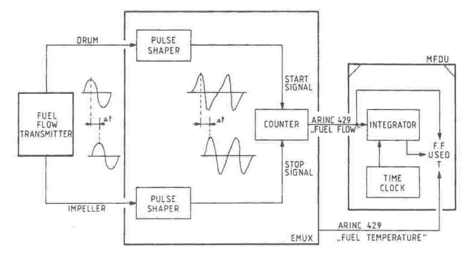
Figure: Calculation and Display