

2.2.1.2. Engine Oil
Oil system indicators generally consists of oil temperature, pressure, and quantity.
Many cockpits include warning lights for low oil pressure and for filter bypass if contaminated.

Figure: Engine Oil System
Pressure
Taken from an external oil line at the accessories gearbox.
Temperature
Taken by a sensor in an external line at the supply line.
Quantity
Taken at the oil tank.
Oil Temperature Indication
The oil temperature indicating system consists of a resistance bulb and an indicator in a 28V DC powered circuit. The bulb contains a temperature-sensitive pure-nickel wire wound around a mica core contained in a steel outer casing. The bulb is installed in an oil line with the tip of the bulb protruding into the oil stream.
The circuit shows the resistance bulb as the variable resistor in a wheatstone bridge-type circuit. Bulb resistance increases when heated and, as this occurs, more and more current flows throu the meter This milliampere circuit flow gives an indication of oil temperature in the cockpit.

Figure: Indicating System

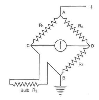
Fig: Temperature Bulb Fig: Wheatstone Bridge with Temperature Bulb
Ratiometer Instrument
An other solution for temperature indication is to use an instrument with two coils.
Coil 1 with the bulb in serie will move the pointer according the sensed oil temperature toward right direction of the scale.
Coil 2 is in serie with a fixed resistor. The magnetic field of this coil moves the pointer toward left direction of the instrument.
The two coils together will compensate any instability of the supply voltage from the aircraft.

Figure: Ratiometer Instrument

Figure: Temperature Bulb wit Ratiometer Instrument
Oil Quantity Indication
A magnet located on the float controls the reed switches. The current to the indicator depends on the resistance inside the probe.

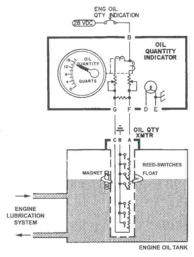
Figure: Quantity Probe Figure: Quantity Indication Schematic
Oil Pressure Indication
Depending on oil pressure the iron core inside the transmitter is moved in a position. The pointer of the oil pressure indicator is moved accordingly.
There are two basic methods used to measure fluid pressure: the Bourdon tube or a capsule. Typical fluid pressures being measured on the aircraft include hydraulic oil and fuel.
The Bourdon tube was invented by Eugиne Bourdon (1808-84), a French watchmaker and engineer. The pressure-sensing element is a tube with either a flat or elliptical section; it is formed as a spiral or curve, see Fig. One end of the tube is sealed and connected to a pointer mechanism, the open end is connected to the fluid system via a pipe.

Figure Bourdon tube principles
As the applied pressure from the fluid system increases, the tube will tend to straighten out, while a reduced pressure will cause the tube to return to its original shape. This movement is transferred via the gear mechanism to move a pointer. The pointer moves across a scale thereby providing a direct reading of pressure. Materials used for the tube are selected for the pressure range being measured; these include phosphor bronze (0-1000 psi) and beryllium copper (0-10,000 psi). The Bourdon tube principle can also be used to remotely measure pressure, see Fig.
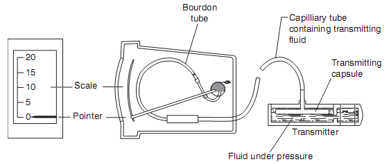
Figure Bourdon tube/remote pressure sensing
The other method used for measuring fluid pressure is with a capsule, see Fig. As pressure is applied by the fluid, the capsule expands. This moves an iron bobbin within the envelope of two inductor coils.

Figure Pressure transducer
These coils are part of an AC ratiometer system as illustrated in Fig. 9.18. The linear shaded pole motors are single-phase induction motors. An unbalance of currents in the inductor coil circuits is caused by displacement of the cores within the coil. Current then flows in one of two directions into the motor circuits. The rotors of the motor are the aluminium discs attached to a shaft. This arrangement produces a low starting torque to produce a responsive indicating system.

Figure AC ratiometer
An alternative arrangement is to connect the iron bobbin to a micro-switch to provide indications of low/high pressure. The advantage of this capsule system is that pressure pipes do not need to be run all the way up to the cockpit indicators.
At the engine close to the oil pressure transmitter there are two switches:
Oil low pressure caution. Warning if oil pressure drops below 35 psi
Oil filter differential pressure. Warning if filter is contaminated (clog)

Figure: Transmitter and Switches located at Engine

Figure: Engine Oil Pressure Indication