

Variable reluctance
The N1 variable reluctance speed transducer comprises a coil wound onto a permanent magnet core as shown in Fig. 5. This type of sensor is found on most gas turbine engines. When the blade tip passes the sensor, the magnetic field is disturbed. This induces a voltage into the coil; as the shaft speed increases the fan tips pass the sensor at an increase rate. The output from the coil is in the form of voltage ' spikes'. These are counted by a processor and used to determine engine speed. Some engines are fitted with a low permeability material inserted into the blade tip to provide a distinctive pulse each time that a specific blade passes the sensor.

Figure 5 N1 engine speed indication
The N2 speed transducer is located within the accessory gearbox, see Fig. 6. A gearbox-driven target wheel contains a permanent magnet inserted on the periphery of the wheel. The coil/core sensor field is disturbed each time that the target passes the sensor. The output is supplied into a processor that drives the indicator.

Figure 6 N2 engine speed indication
Engine temperature
Exhaust gas temperature is a primary gas turbine engine indication. Engine temperature is closely monitored at all times, particularly during start and takeoff, to make sure that engine limits are not exceeded. It is sometimes referred to as:
• turbine inlet temperature (TIT)
• inter-turbine temperature (ITT)
• turbine outlet temperature (TOT)
• exhaust gas temperature (EGT)
• turbine gas temperature (TGT)
• jet pipe temperature (JPT).
The type of measurement depends on where the probe is located and according to individual engine manufacturer's terminology; Fig. 7 illustrates some of these locations. The turbine section runs at very high temperatures, typically 1000°C; the transducer used in this application is the thermocouple (sometimes referred to as a ' temperature probe ').
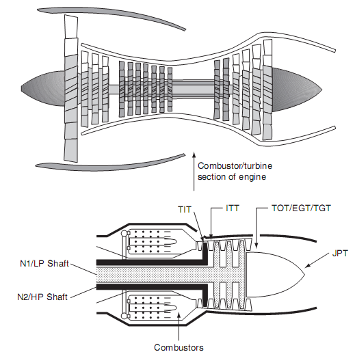
Figure 7 Engine temperature measurement
A typical engine temperature measurement system is illustrated in Fig. 8. On larger engines, it is possible to have a range of temperatures in the exhaust zone due to the turbulence of gases.
Some installations feature a thermocouple that has two or even three hot junctions within the same outer tube. This arrangement provides an average of temperature within the zone to provide an average temperature at different immersion distances in the engine, see Fig. 9.
Thermocouple junctions alone do not generate electromotive force (e.m.f.). The potential difference that develops at the heated junction is a function of both the hot and cold junction temperatures.
Small gas turbine engines are normally fitted with several thermocouples to provide an average temperature and some redundancy in case of failure. Larger engines can be fitted with up to 21 thermocouples; these are connected in parallel to provide an average reading of the gas temperature in the exhaust zone. The interconnecting cables between the thermocouple(s) and indicator have to be the same material throughout the system otherwise addition junctions will be formed, thereby generating unwanted voltages. A typical thermocouple cable installation is shown in Fig. 10.
Thermocouple cables are colour-coded to reduce the likelihood of different materials being cross-connected, or mixed in the same installation (note that these codes vary in some countries; always refer to the maintenance manual):
nickel-chrome (white)
nickel-aluminium (green)
iron (black)
constantan (yellow)
copper (red).

Figure 8 Engine temperature system

Figure 9 Average temperature measurement Figure 10 Thermocouple/cable installation
On piston engines, the EGT indication has a different application; it is used to adjust the fuel-air mixture for economical running of the engine. The thermocouple is located in located in the exhaust system, reducing the amount of fuel into the cylinders (called leaning the mixture); this results in a more efficient combustion and the exhaust temperature increases. When this temperature reaches a peak, maximum efficiency has been achieved. Using one thermocouple per cylinder averages out individual differences and provides enhanced fuel efficiencies.
Piston engines also use thermocouples to monitor the cylinder head temperature (CHT). This indication is used to monitor the temperature of an air-cooled engine. The system can be arranged with either one CHT thermocouple per cylinder or just one CHT thermocouple per engine. In the latter case, the thermocouple is installed in the hottest running cylinder; on a horizontally opposed engine this would be the rear cylinder. The thermocouple can be formed to fit under the spark plug or directly into the head itself. The advantage of monitoring each cylinder is that trend indications can be derived.
Engine pressure ratio (EPR)
This is a primary gas turbine engine indication system and is one of two methods used to indicate thrust (the alternative method is described under engine speed). The principle of an EPR indication system is to measure the exhaust and inlet pressures and derive a ratio between them. EPR probes are located at the inlet and exhaust of the engine, see Fig. 11. The inlet pressure probe is a single device, located in the nacelle; there can be several exhaust probes connected via a manifold.

Figure 11 EPR schematic
Pressures from the inlet and exhaust are sent via small diameter pipes to the EPR transducer; this comprises pressure sensors (capsules). These are coupled to a mechanism that determines the displacement of the capsules as ratio. Outputs from the ratio sensor are sent via a linear variable differential transformer (LVDT) to the indicator. The EPR signal from the transducer is transmitted as a voltage to the indicator. The typical range of EPR indications is between one and two.
Fuel flow
This is a primary engine indication for which there are various types of transducer; these are located in the fuel delivery pipeline. A typical transducer type is based on the metering vane principle; see lecture 2.5. The metering vane is attached to a shaft; this rotates when the fuel supply passes through the body of the transducer. The circular chamber has sufficient clearance to allow fuel to pass through with minimal restriction.
Rotation of the vane is opposed by a spring; the angular position of the vane is measured and indicated by a synchro system, see lecture 2.5. The metering vane system gives an indication of volume flow, e.g. gallons or litres of fuel flow per hour.
An alternative fuel flow transducer is the motor-driven impeller principle; see lecture 2.5. An impeller is driven at a constant speed by an AC synchronous motor. The fuel that flows through the impeller is imparted with a rotational force; this causes the turbine blades to rotate against the force of a spring. The speed of turbine rotation is therefore proportional to fuel flow. Denser fuel imparts more energy into the turbine; the transducer is therefore measuring mass flow. The turbine is connected to the indicator via a synchro system; typical units of mass flow are given in pounds or kilograms of fuel per hour.
Torque
The power delivered by the engine to the propeller shaft can be derived from the relationship:
Power = torque X speed
Power is derived from measuring both torque and speed; the indication is normally used for turboprops and helicopter rotors. Indicators are calibrated in a percentage of maximum torque or shaft horsepower (SHP). A typical torque indicator used on a twin-engined helicopter is shown in Fig. 12.


Fig 12 Typical helicopter torque indicator (twin engine) Figure 13 Torque transducer principles
Indications are given for the output from both engines and main rotor (M/R) torque. This is the most effective way of indicating the power being produced by the engine.
There are several methods used to measure torque. The torque shaft is formed with toothed or phonic wheels, see Fig. 13. As the applied torque changes the phase difference between the signals obtained from the two speed sensors increases. The torque applied to the shaft results in a phase difference between the outputs of the two sensors, see Fig. 14.


Figure 14 Shaft torque sensor phase differences (a) no load conditions, (b) engine lightly loaded, (c) engine heavily loaded.
Torque can also be measured by embedding strain gauges into the shaft to measure the deformation (strain) of the shaft; these can either be metallic foil or semiconductor piezo-resistors.