

Instruments lights
Internal instrument lighting is normally from incandescent lamps integrated within individual instruments; lighting must be shielded from causing any direct glare to the pilot and must be dimmable. External instrument lighting is provided by pillar (or bridge) lights positioned on the panels for individual instruments. The light intensity can be dimmed by a simple rheostat device as illustrated in Fig. 3; this typical circuit is for flight instruments, engine instruments and switch panels.
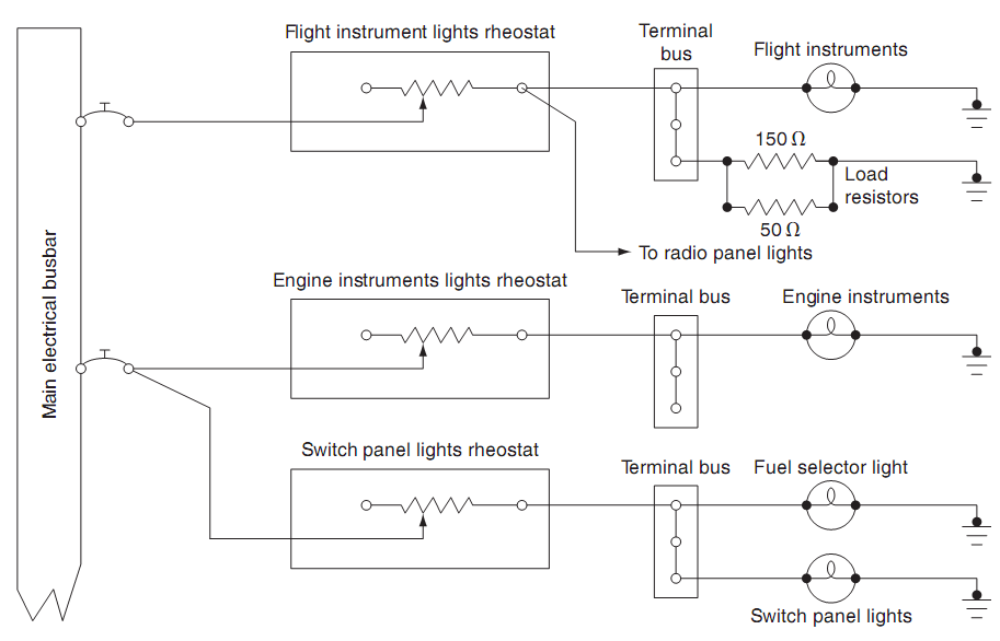
Figure 3 Rheostat light intensity control
The increased quantity of instruments requires electronic control in place of rheostat due to the higher loads. A transistor circuit provides electronic control as illustrated in Fig. 4; variable resistor RV1 varies the (relatively low) base current into the base of a PNP transistor; this controls the (relatively high) current through the collector and lamp. A typical transistor controlled lighting system is illustrated Fig. 5. The relatively low base currents in the respective transistors can now control a variety of lighting circuits:
• radio navigation systems
• compass
• fuel panels
• engine indications.
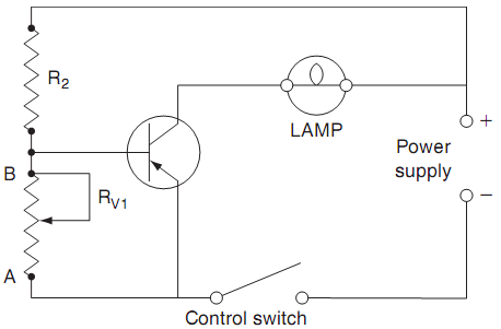
Figure 4 Transistor lighting control circuit
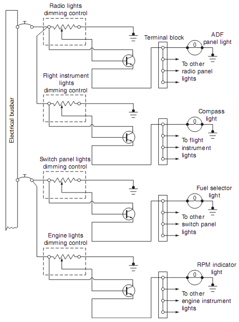
Figure 5 Transistor lighting control system
Instrument panels are often constructed from Perspex; the surface is painted and then engraved with the identification of switches and controls; the panel is illuminated from the edges. The light is dispersed through the panel, but is only seen through the engravings. Alternatively, electro-luminescent panels are used; these are AC powered and energy efficient. Referring to Fig. 6, the phosphorus layer is laminated between front and rear clear plastic layers. The phosphorus material glows when AC power is applied; the front of the panel is painted to match the colour of other panels. Engraved lettering or symbols remain clear and transmit light from the glowing phosphorus layer.
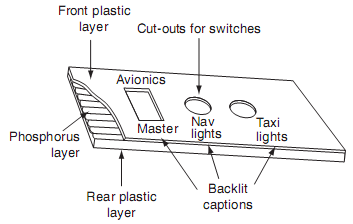
Figure 6 Phosphorus lighting panel
Master warning lights
An increasing number of systems are being designed into aircraft; this leads to more warning lights and larger panels with an increased possibility of a warning light being missed by the crew. This has led to centralized 'attention getters', or master warning and caution light panels, a typical arrangement is shown in Fig. 7. The lights are located within pilot's immediate view, typically on the glareshield. Master caution and warning systems were developed to ease pilot workload, particularly on aircraft designed for operation without a flight engineer. In addition to the attention getter, it also directs the pilot towards the problem area concerned. The system annunciators are usually arranged such that the cautions are in the same orientation as the main system panels, e.g. the overhead panel.
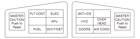
Figure 7 Master warning and caution lights
A simplified master warning circuit is illustrated in Fig. 8. In this example, switch contacts 1 and 2 represent the individual warning signals from two different systems. In the event of a failure or malfunction, closure of either switch causes its corresponding warning light to illuminate together with the master warning (MW) light. The master warning and caution light is cancelled by pressing the light caption, whilst the crew react and investigate the reason for the warning. Typical panels could have up to 50 individual warning lights, any one of which also illuminates the master warning light. The individual lights could be located on an overhead or side panel.
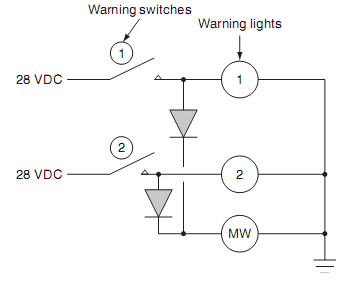
Figure 8 Simplified master warning circuit
A diode is required in the warning light circuit to ensure that only the relevant system light is illuminated.
When the master warning or caution light is illuminated, the pilot cross-refers to a centralized group of warning lights on the relevant panel, each connected to the warning devices of specific systems. The individual systems are identified by the system name and are located within the pilot's scan. Warning lights can be tested by a separate t est switch, or by a centralized master dim and test switch. The night/day switch is used to reduce the intensity of warning lights during low ambient lighting conditions. Referring to Fig. 9(a), warning and caution lights affecting system operation and aircraft safety are defined by specific colours:
• warning, red, an unsafe condition exists
• caution, amber, an abnormal condition exists, but it is not unsafe
• advisory, green or blue, a safe condition exists, or for information e.g. gear down.
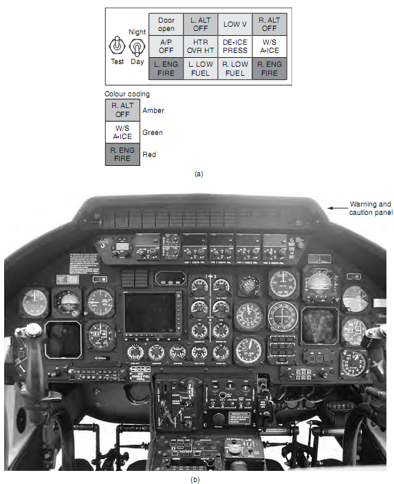
Figure 9 Warning and caution panels: (a) typical arrangement, (b) helicopter installation
Some installations have a comprehensive master warning and caution light panel that occupies the entire upper instrument panel, see Fig. 9(b).
Emerging technology
Digital technology is replacing traditional wire bundles from the flight compartment to the equipment bays. A digital processor on each warning and caution module replaces lighted switches with the associated wire bundles. LEDs can now provide sufficient brightness to replace incandescent lighting with 30% power reduction compared with fluorescent lighting. The objectives are to accomplish weight, cost and reliability goals while giving flight crews what they are used to seeing in older flight compartments, including the tactile feel for push buttons and controls for lighting and dimming.
Lights used for certain warnings are not dimmable, e.g. fire and overheat. This is to ensure that the warnings are not missed under bright ambient lighting conditions.