

Introduction to 3D Game Programming with DirectX.9.0 - F. D. Luna
.pdf184 Chapter 11
In the Display function we rotate the mesh slightly every frame so that it spins. The mesh can be rendered trivially using a simple loop since the subsets are labeled in the order 0, 1, 2, …, n – 1, where n is the number of subsets:
bool Display(float timeDelta)
{
if( Device )
{
//
// Update: Rotate the mesh.
// |
|
|
L |
|
|
F |
|
static float y = 0.0f; |
|
||
D3DXMATRIX yRot; |
|
|
|
|
M |
||
D3DXMatrixRotationY(&yRot, y);Y |
|||
y += timeDelta; |
|
|
|
A |
|
||
if( y >= 6.28f ) |
|
|
|
y = 0.0f; |
|
|
|
E |
|
|
|
D3DXMATRIX World = yRot; |
|||
T |
|
|
|
Device->Set ransform(D3DTS_WORLD, &World);
//
// Render
//
Device->Clear(0, 0, D3DCLEAR_TARGET | D3DCLEAR_ZBUFFER,
0xffffffff, 1.0f, 0);
Device->BeginScene();
for(int i = 0; i < Mtrls.size(); i++)
{
Device->SetMaterial( &Mtrls[i] ); Device->SetTexture(0, Textures[i]); Mesh->DrawSubset(i);
}
Device->EndScene(); Device->Present(0, 0, 0, 0);
}
return true;
}
11.2.4 Generating Vertex Normals
It is possible that an XFile does not contain vertex normal data. If this is the case, it may be necessary to compute the vertex normals manually so that we can use lighting. We briefly outlined how to do this way back in Chapter 5. However, now that we know about the ID3DXMesh
Team-Fly®

Meshes Part II 185
interface and its parent ID3DXBaseMesh, we can use the following function to generate vertex normals for any mesh:
HRESULT D3DXComputeNormals(
LPD3DXBASEMESH pMesh, |
// |
Mesh to compute |
normals of. |
const DWORD *pAdjacency |
// |
Input adjacency |
info. |
);
This function generates the vertex normals by using normal averaging. If adjacency info is provided, then duplicated vertices are disregarded. If adjacency info is not provided, then duplicated vertices have normals averaged from the faces that reference them. It is important to realize that the mesh we pass in for pMesh must have a vertex format that contains the D3DFVF_NORMAL flag.
Note that if an XFile does not contain vertex normal data, the ID3DXMesh object created from D3DXLoadMeshFromX does not have the D3DFVF_NORMAL flag specified in its vertex format. Therefore, before we can use D3DXComputeNormals, we have to clone the mesh and specify a vertex format for the cloned mesh that includes D3DFVF_NORMAL. The following example demonstrates this:
// does the mesh have a D3DFVF_NORMAL in its vertex format? |
|
|
if ( !(pMesh->GetFVF() & D3DFVF_NORMAL) ) |
|
|
{ |
|
|
// no, so clone a new mesh and add D3DFVF_NORMAL to its format: |
|
|
ID3DXMesh* pTempMesh = 0; |
|
|
pMesh->CloneMeshFVF( |
|
|
D3DXMESH_MANAGED, |
|
|
|
|
|
pMesh->GetFVF() | D3DFVF_NORMAL, // add it here |
|
I |
Device, |
|
II |
&pTempMesh ); |
|
t |
// compute the normals: |
|
Par |
D3DXComputeNormals( pTempMesh, 0 ); |
|
|
pMesh->Release(); // get rid of the old mesh |
|
|
pMesh = pTempMesh; // save the new mesh with normals |
|
|
} |
|
|
11.3 Progressive Meshes
Progressive meshes, represented by the ID3DXPMesh interface, allow us to simplify a mesh by applying a sequence of edge collapse transformations (ECT). Each ECT removes one vertex and one or two faces. Because each ECT is invertible (its inverse is called a vertex split), we can reverse the simplification process and restore the mesh to its exact original state. This, of course, means that we cannot obtain a mesh more detailed then the original; we can only simplify and then reverse

186 Chapter 11
those simplification operations. Figure 11.2 shows a mesh at three different levels of detail (LOD): high, medium, and low.
Figure 11.2: A mesh shown at three different resolutions
The idea of progressive meshes is analogous to using mipmaps for textures. When texturing, we noticed that it was wasteful to use a high-resolution texture for a small, far-away primitive where the extra detail would go unnoticed. The same goes for meshes; a small, far-away mesh does not need as high a triangle count as a large, close-up mesh because the extra triangle detail for the small mesh would go unnoticed. Thus, we would end up spending time rendering a high triangle count model when a simpler low triangle count model would suffice.
One way that we can use progressive meshes is to adjust the LOD of a mesh based on its distance from the camera. That is, as the distance decreases, we would add detail (triangles) to the mesh, and as the distance increased we would remove detail.
Note that we do not discuss how progressive meshes can be implemented; rather we show how to use the ID3DXPMesh interface. For those readers interested in the implementation details, you can find the original progressive mesh papers at Hugues Hoppe’s web site: http://research.microsoft.com/~hoppe/.
11.3.1 Generating a Progressive Mesh
We can create an ID3DXPMesh object using the following function:
HRESULT D3DXGeneratePMesh(
LPD3DXMESH pMesh,
CONST DWORD *pAdjacency,
CONST LPD3DXATTRIBUTEWEIGHTS pVertexAttributeWeights, CONST FLOAT *pVertexWeights,
DWORD MinValue,
DWORD Options, LPD3DXPMESH *ppPMesh
);
pMesh—An input mesh that contains the data of the mesh from which we want to generate a progressive mesh

Meshes Part II
pAdjacency—Pointer to a DWORD array that contains the adjacency info of pMesh
pVertexAttributeWeights—Pointer to a D3DXATTRIBUTEWEIGHTS array of size pMesh->GetNumVertices(), where the ith entry corresponds with the ith vertex in pMesh and specifies its attribute weight. The attribute weights are used to determine the chance that a vertex is removed during simplification. You can pass in null for this parameter and a default vertex attribute weight will be used for each vertex. See section 11.3.2 for more information on attribute weights and the D3DXATTRIBUTEWEIGHTS structure.
pVertexWeights—Pointer to a float array of size pMesh-> GetNumVertices(), where the ith entry corresponds to the ith vertex in pMesh and specifies its vertex weight. The higher a vertex weight, the less chance it has of being removed during simplification. You can pass in null for this parameter and a default vertex weight of 1.0 will be used for each vertex.
MinValue—The minimum vertices or faces (determined by the next parameter—Options) we want to simplify down to. Note that this value is a request, and depending on vertex/attribute weights the resulting mesh might not match this value.
Options—Exactly one member of the D3DXMESHSIMP enumerated type:
D3DXMESHSIMP_VERTEX—Specifies that the previous parameter MinValue refers to vertices
D3DXMESHSIMP_FACE—Specifies that the previous parameter MinValue refers to faces
ppPMesh—Returns the generated progressive mesh
11.3.2 Vertex Attribute Weights
typedef struct _D3DXATTRIBUTEWEIGHTS { FLOAT Position;
FLOAT Boundary;
FLOAT Normal;
FLOAT Diffuse;
FLOAT Specular;
FLOAT Texcoord[8];
FLOAT Tangent;
FLOAT Binormal;
} D3DXATTRIBUTEWEIGHTS;
187
P a r t I I I
The vertex weight structure allows us to specify a weight for each possible component of a vertex. A value of 0.0 would indicate that the component carries no weight. The higher the weights for the vertex

188 Chapter 11
components, the less likely the vertex will be removed in simplification. The default weights are as follows:
D3DXATTRIBUTEWEIGHTS AttributeWeights;
AttributeWeights.Position = 1.0;
AttributeWeights.Boundary = 1.0;
AttributeWeights.Normal |
= 1.0; |
AttributeWeights.Diffuse |
= 0.0; |
AttributeWeights.Specular |
= 0.0; |
AttributeWeights.Tex[8] |
= {0.0, 0.0, 0.0, 0.0, 0.0, 0.0, 0.0, 0.0}; |
The default weights are recommended, unless the application has a significant reason not to use them.
11.3.3 ID3DXPMesh Methods
The ID3DXPMesh interface inherits from the ID3DXBaseMesh interface. It therefore has all the functionality of the previously studied ID3DXMesh, as well as the following (but not limited to) additional methods:
DWORD GetMaxFaces(VOID);—Returns the maximum number of faces that the progressive mesh can be set to have
DWORD GetMaxVertices(VOID);—Returns the maximum number of vertices that the progressive mesh can be set to have
DWORD GetMinFaces(VOID);—Returns the minimum number of faces that the progressive mesh can be set to have
DWORD GetMinVertices(VOID);—Returns the minimum number of vertices that the progressive mesh can be set to have
HRESULT SetNumFaces(DWORD Faces);—This method allows us to set the number of faces that we want the mesh to be simplified/complexified to. For example, suppose that the mesh presently has 50 faces and we want to simplify it to 30 faces; we would write:
pmesh->SetNumFaces(30);
Note that after the adjustment the number of faces of the mesh may differ by one from the number desired. If Faces is less than GetMinFaces(), it is clamped to GetMinFaces(). Similarly, if Faces is greater than GetMaxFaces(), it is clamped to
GetMaxFaces().
HRESULT SetNumVertices(DWORD Vertices);—This method allows us to set the number of vertices that we want the mesh to be simplified/complexified to. For example, suppose the mesh presently has 20 vertices and we want to add detail to it by increasing the vertex count to 40 vertices; we would write:

Meshes Part II 189
pmesh->SetNumVertices(40);
Note that the number of vertices of the mesh, after the adjustment, may differ by one from the number desired. If Vertices is less than GetMinVertices(), it is clamped to GetMinVertices(). Similarly, if Vertices is greater than GetMaxVertices(), it is clamped to GetMaxVertices().
HRESULT TrimByFaces(
DWORD NewFacesMin,
DWORD NewFacesMax,
DWORD *rgiFaceRemap, // Face remap info. DWORD *rgiVertRemap // Vertex remap info.
);
This method allows us to set a new face count minimum and maximum, as specified by the arguments NewFacesMin and NewFacesMax, respectively. Note that the new minimum and maximum must be in the present face minimum and maximum interval; that is, it must be in [GetMinFaces(), GetMaxFaces()]. The function also returns face and vertex remap information. See section 10.4 for a description of remap information.
HRESULT TrimByVertices(
DWORD NewVerticesMin,
DWORD NewVerticesMax,
DWORD *rgiFaceRemap, // Face remap info. DWORD *rgiVertRemap // Vertex remap info.
);
This method allows us to set a new vertex count minimum and maximum as specified by the arguments NewVerticesMin and NewVerticesMax, respectively. Note that the new minimum and maximum must be in the present vertex minimum and maximum interval; that is, it must be in [GetMinVertices(), GetMaxVertices()]. The function also returns face and vertex remap information. See section 10.4 for a description of remap information.
P a r t I I I
Note: Of particular interest are the methods SetNumFaces and SetNumVertices, for these methods are the ones that allow us to adjust the LOD of the mesh.

190Chapter 11
11.3.4Sample Application: Progressive Mesh
The Progressive Mesh sample is similar to the XFile sample, except for the fact that the mesh we create and render is a progressive mesh and thus represented by the ID3DXPMesh interface. We allow the user to change the resolution of the progressive mesh interactively via keyboard input. You can add faces to the mesh by pressing the A key, and you can remove faces from the mesh by pressing the S key.
The global variables used in the sample are almost the same as those used in the XFile sample, but we add an additional variable to store the progressive mesh:
ID3DXMesh* |
SourceMesh |
= 0; |
ID3DXPMesh* |
PMesh |
= 0; // progressive mesh |
std::vector<D3DMATERIAL9> |
Mtrls(0); |
|
std::vector<IDirect3DTexture9*> Textures(0);
Recall that to generate a progressive mesh we must pass in a “source” mesh that contains the data we want to create a progressive mesh of. Thus, we first load the XFile data into an ID3DXMesh object SourceMesh and then generate the progressive mesh:
bool Setup()
{
HRESULT hr = 0;
//...Load XFile data into SourceMesh snipped.
//...Extracting materials and textures snipped.
Since the code to do this is exactly the same as it was in the XFile sample, we have omitted it. Once we have a source mesh, we can generate the progressive mesh as follows:
//
// Generate the progressive mesh.
//
hr = D3DXGeneratePMesh( SourceMesh,
(DWORD*)adjBuffer->GetBufferPointer(), // adjacency
0, |
// default vertex attribute weights |
0, |
// default vertex weights |
1, |
// simplify as low as possible |
D3DXMESHSIMP_FACE, |
// simplify by face count |
&PMesh); |
|
d3d::Release<ID3DXMesh*>(SourceMesh); // done w/ source mesh d3d::Release<ID3DXBuffer*>(adjBuffer); // done w/ buffer
if(FAILED(hr))
{

Meshes Part II 191
::MessageBox(0, "D3DXGeneratePMesh() - FAILED", 0, 0); return false;
}
Note that while we request to simplify the mesh down to one face, this will usually not occur due to vertex/attribute weights; however, specifying 1 will reduce the mesh to its lowest resolution.
At this point, the progressive mesh has been generated but if we render it now, it will be rendered at its lowest resolution. Because we want to initially render the mesh at full resolution, we set it to:
// set to original (full) detail DWORD maxFaces = PMesh->GetMaxFaces(); PMesh->SetNumFaces(maxFaces);
In the Display function, we test for an A keypress and an S keypress and handle the input accordingly:
bool Display(float timeDelta)
{
if( Device )
{
//
// Update: Mesh resolution.
//
// Get the current number of faces the pmesh has. int numFaces = PMesh->GetNumFaces();
// Add a face, note the SetNumFaces() will automatically |
|
// clamp the specified value if it goes out of bounds. |
|
|
|
if( ::GetAsyncKeyState('A') & 0x8000f ) |
I |
{ |
II |
|
|
// Sometimes we must add more than one face to invert |
t |
// an edge collapse transformation because of the internal |
ar |
// implementation details of the ID3DXPMesh interface. In |
P |
|
|
// other words, adding one face may possibly result in a |
|
|
|
// mesh with the same number of faces as before. Thus to |
|
// increase the face count we may sometimes have to add |
|
// two faces at once. |
|
PMesh->SetNumFaces(numFaces + 1); |
|
if(PMesh->GetNumFaces() == numFaces) |
|
PMesh->SetNumFaces(numFaces + 2); |
|
} |
|
//Remove a face, note the SetNumFaces() will automatically
//clamp the specified value if it goes out of bounds. if(::GetAsyncKeyState('S') & 0x8000f)
PMesh->SetNumFaces(numFaces - 1);
This is straightforward, but notice that when adding a face we must sometimes add two faces in order to invert an edge collapse transformation.

192 Chapter 11
To conclude, we can render an ID3DXPMesh object the same way that we render an ID3DXMesh object. In addition, we also outline the mesh’s triangles in yellow by drawing the mesh in wireframe mode with a yellow material. We do this so that we can see the individual triangles being added and removed by the progressive mesh when we adjust the LOD.
Device->Clear(0, 0, D3DCLEAR_TARGET | D3DCLEAR_ZBUFFER,
0xffffffff, 1.0f, 0);
Device->BeginScene();
for(int i = 0; i < Mtrls.size(); i++)
{
Device->SetMaterial( &Mtrls[i] ); Device->SetTexture(0, Textures[i]); PMesh->DrawSubset(i);
// draw wireframe outline
Device->SetMaterial(&d3d::YELLOW_MTRL); Device->SetRenderState(D3DRS_FILLMODE, D3DFILL_WIREFRAME); PMesh->DrawSubset(i); Device->SetRenderState(D3DRS_FILLMODE, D3DFILL_SOLID);
}
Device->EndScene(); Device->Present(0, 0, 0, 0);
}
return true;
} // end Display
Figure 11.3: A screen shot of the Progressive Mesh sample
Meshes Part II 193
11.4 Bounding Volumes
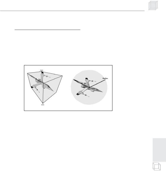
Sometimes we want to compute a bounding volume of a mesh. Two common examples of the bounding volumes used are spheres and boxes. Other examples are cylinders, ellipsoids, lozenges, and capsules. Figure 11.4 shows a mesh with a bounding sphere and the same mesh with a bounding box. For this section we work only with bounding boxes and bounding spheres.
Figure 11.4: A mesh rendered with its bounding sphere and bounding box. A sphere can be defined by its center point and radius. A box can be defined by its minimum and maximum points.
Bounding boxes/spheres are often used to speed up visibility tests and collision tests, among other things. For example, we can say that a mesh is not visible if its bounding box/sphere is not visible. A box/ sphere visibility test is much cheaper than individually testing the visibility of each triangle in the mesh. For a collision example, suppose that a missile is fired in the scene and we want to determine if the missile hit an object in the scene. Since the objects are made up of triangles, we could iterate through each triangle of each object and test if the missile (modeled mathematically by a ray) hit a triangle of the object. This approach would require many ray/triangle intersection tests—one for each triangle of each object in the scene. A more efficient approach would be to compute the bounding box/sphere of each mesh and then do one ray/box or ray/sphere intersection test per object. We can then say that the object is hit if the ray intersected its bounding volume. This is a fair approximation; if more precision is necessary, we can use the ray/box or ray/sphere to quickly reject objects that are obviously not going to be hit and then apply a more precise test to objects that have a good chance of being hit. Objects that have a good chance of being hit are objects whose bounding volumes were hit.
The D3DX library provides functions to calculate the bounding sphere of a mesh and the bounding box of a mesh. These functions take an array of vertices as input to compute the bounding sphere or box.
P a r t I I I