

Introduction to 3D Game Programming with DirectX.9.0 - F. D. Luna
.pdf94 Chapter 4
const D3DXCOLOR |
YELLOW( |
D3DCOLOR_XRGB(255, |
255, |
0) |
); |
const D3DXCOLOR |
CYAN( |
D3DCOLOR_XRGB( 0, |
255, 255) |
); |
|
const D3DXCOLOR |
MAGENTA( |
D3DCOLOR_XRGB(255, |
0, |
255) |
); |
}
4.2 Vertex Colors
The color of a primitive is determined by the color of the vertices that make it up. Therefore, we must add a color member to our vertex data structure. Note that a D3DCOLORVALUE type cannot be used here because Direct3D expects a 32-bit value to describe the color of a vertex. (Acually, by using a vertex shader we could use 4D color vectors
for the vertex color, and thereby gain 128-bit color, but that is getting |
||||||
|
|
|
|
|
|
Y |
ahead of ourselves for now. Vertex shaders are covered in Chapter 17.) |
||||||
|
|
|
|
|
L |
|
|
struct ColorVertex |
|
F |
|||
|
{ |
|
|
|
||
|
|
float _x, _y, z; |
||||
|
|
M |
|
|||
|
|
D3DCOLOR _color; |
|
|||
|
|
|
|
|
|
|
|
|
|
|
A |
|
|
|
|
|
E |
|
||
|
|
|
T |
|
|
|
static const DWORD FVF;
}
const DWORD ColorVertex::FVF = D3DFVF_XYZ | D3DFVF_DIFFUSE;
4.3 Shading
Shading occurs during rasterization and specifies how the vertex colors are used to compute the pixel colors that make up the primitive. There are two shading modes that are presently used: flat shading and Gouraud shading.
With flat shading, the pixels of a primitive are uniformly colored by the color specified in the first vertex of the primitive. So the triangle formed by the following three vertices would be red, since the first vertex color is red. The colors of the second and third vertices are ignored with flat shading.
ColorVertex t[3];
t[0]._color = D3DCOLOR_XRGB(255, 0, 0);
t[1]._color = D3DCOLOR_XRGB(0, 255, 0); t[2]._color = D3DCOLOR_XRGB(0, 0, 255);
Flat shading tends to make objects appear blocky because there is no smooth transition from one color to the next. A much better form of shading is called Gouraud shading (also called smooth shading). With Gouraud shading, the colors at each vertex are interpolated linearly across the face of the primitive. Figure 4.2 shows a red flat shaded triangle and a triangle colored using Gouraud shading.
Team-Fly®

Color 95
Figure 4.2: On the left is a triangle colored red with flat shading. On the right is a triangle with vertex colors red, green, and blue; notice that with Gouraud shading, the vertex colors are interpolated across the triangle.
Like many things in Direct3D, the shading mode is controlled through the Direct3D state machine.
// set flat shading Device->SetRenderState(D3DRS_SHADEMODE, D3DSHADE_FLAT);
// set Gouraud shading Device->SetRenderState(D3DRS_SHADEMODE, D3DSHADE_GOURAUD);
4.4 Sample Application: Colored Triangle
The sample program for this chapter demonstrates a triangle colored using flat shading and a triangle colored using Gouraud shading. It renders the image shown in Figure 4.2. First we add the following global variables:
D3DXMATRIX |
World; |
IDirect3DVertexBuffer9* Triangle = 0;
We include a D3DXMATRIX that is used to store the world transformation of the triangles that we are going to draw. The Triangle variable is the vertex buffer that stores the vertex data of a triangle. Notice that we only have to store the geometry of one triangle because we can draw it multiple times at different positions in the world using the world matrix.
The Setup method creates the vertex buffer and fills it with the data of a triangle with colored vertices. The first vertex in the triangle is full-intensity red (255), the second is full-intensity green (255), and the third is full-intensity blue (255). Finally, we disable lighting for this sample. Notice that this sample uses the new ColorVertex structure, as explained in section 4.2.
P a r t I I

96 Chapter 4
bool Setup()
{
// create vertex buffer Device->CreateVertexBuffer(
3 * sizeof(ColorVertex), D3DUSAGE_WRITEONLY, ColorVertex::FVF, D3DPOOL_MANAGED, &Triangle,
0);
// fill the buffers with the triangle data ColorVertex* v;
Triangle->Lock(0, 0, (void**)&v, 0);
v[0] = ColorVertex(-1.0f, 0.0f, 2.0f, D3DCOLOR_XRGB(255, |
0, |
|
|
0)); |
|
v[1] = ColorVertex( 0.0f, 1.0f, 2.0f, D3DCOLOR_XRGB( |
0, 255, |
|
|
0)); |
|
v[2] = ColorVertex( 1.0f, 0.0f, 2.0f, D3DCOLOR_XRGB( |
0, |
0, |
255));
Triangle->Unlock();
// set projection matrix D3DXMATRIX proj; D3DXMatrixPerspectiveFovLH(
&proj,
D3DX_PI * 0.5f, // 90 - degree (float)Width / (float)Height, 1.0f,
1000.0f); Device->SetTransform(D3DTS_PROJECTION, &proj);
// set the render states Device->SetRenderState(D3DRS_LIGHTING, false);
return true;
}
Then, the Display function draws Triangle twice in two different positions and with different shade modes. The position of each triangle is controlled with the world matrix—World.
bool Display(float timeDelta)
{
if( Device )
{
Device->Clear(0, 0, D3DCLEAR_TARGET | D3DCLEAR_ZBUFFER, 0xffffffff, 1.0f, 0);
Device->BeginScene();
Device->SetFVF(ColorVertex::FVF);
Device->SetStreamSource(0, Triangle, 0, sizeof(ColorVertex));

Color 97
// draw the triangle to the left with flat shading D3DXMatrixTranslation(&World, -1.25f, 0.0f, 0.0f); Device->SetTransform(D3DTS_WORLD, &World);
Device->SetRenderState(D3DRS_SHADEMODE, D3DSHADE_FLAT);
Device->DrawPrimitive(D3DPT_TRIANGLELIST, 0, 1);
// draw the triangle to the right with gouraud shading D3DXMatrixTranslation(&World, 1.25f, 0.0f, 0.0f); Device->SetTransform(D3DTS_WORLD, &World);
Device->SetRenderState(D3DRS_SHADEMODE, D3DSHADE_GOURAUD);
Device->DrawPrimitive(D3DPT_TRIANGLELIST, 0, 1);
Device->EndScene(); Device->Present(0, 0, 0, 0);
}
return true;
}
4.5Summary
Colors are described by specifying an intensity of red, green, and blue. The additive mixing of these three colors at different intensities allows us to describe millions of colors. In Direct3D, we can use the D3DCOLOR, the D3DCOLORVALUE, or the D3DXCOLOR type to describe a color in code.
We sometimes treat a color as a 4D vector (r, g, b, a). Color vectors are added, subtracted, and scaled just like regular vectors. On the other hand, dot and cross products do not make sense for color vec-
tors, but component-wise multiplication does make sense for colors. The symbol denotes component-wise multiplication, and it is defined as: (c1, c2, c3, c4) (k1, k2, k3, k4) = (c1k1, c2k2, c3k3, c4k4).
We specify the color of each vertex, and then Direct3D uses the current shade mode to determine how these vertex colors are used to compute the pixel colors of the triangle during rasterization.
With flat shading, the pixels of a primitive are uniformly colored by the color specified in the first vertex of the primitive. With Gouraud shading, the colors at each vertex are interpolated linearly across the face of the primitive.
P a r t I I

Chapter 5
Lighting
To enhance the realism of our scenes, we can add lighting. Lighting also helps to depict the solid form and volume of objects. When using lighting, we no longer specify vertex colors ourselves; rather, Direct3D runs each vertex through its lighting engine and computes a vertex color based on defined light sources, materials, and the orientation of the surface with regard to the light sources. Computing the vertex colors based on a lighting model results in a more natural scene.
Objectives
To learn the light sources that Direct3D supports and types of light that these sources emit
To understand how we define light to interact with the surface that it strikes
To find out how we can mathematically describe the direction a triangle is facing so that we can determine the angle at which a light ray strikes the triangle
5.1Light Components
In the Direct3D lighting model, the light emitted by a light source consists of three components, or three kinds of light.
Ambient Light—This kind of light models light that has reflected off other surfaces and is used to brighten up the overall scene. For example, parts of objects are often lit, to a degree, even though they are not in direct sight of a light source. These parts get lit from light that has bounced off other surfaces. Ambient light is a hack used to roughly, and cheaply, model this reflected light.
Diffuse Light—This type of light travels in a particular direction. When it strikes a surface, it reflects equally in all directions. Because diffuse light reflects equally in all directions, the reflected light will reach the eye no matter the viewpoint, and therefore we do not need to take the viewer into consideration. Thus, the diffuse
98

Lighting 99
lighting equation needs only to consider the light direction and the attitude of the surface. This kind of light will be your general light that emits from a source.
Specular Light—This type of light travels in a particular direction. When it strikes a surface, it reflects harshly in one direction, causing a bright shine that can only be seen from some angles. Since the light reflects in one direction, clearly the viewpoint, in addition to the light direction and surface attitude, must be taken into consideration in the specular lighting equation. Specular light is used to model light that produces highlights on objects, such as the bright shine created when light strikes a polished surface.
Specular lighting requires more computations than the other types of light; therefore, Direct3D provides the option to turn it off. In fact, by default it is turned off; to enable specular lighting you must set the
D3DRS_SPECULARENABLE render state.
Device->SetRenderState(D3DRS_SPECULARENABLE, true);
Each type of light is represented by a D3DCOLORVALUE structure or D3DXCOLOR, which describes the color of the light. Here are some examples of several light colors:
D3DXCOLOR redAmbient(1.0f, 0.0f, 0.0f, 1.0f);
D3DXCOLOR blueDiffuse(0.0f, 0.0f, 1.0f, 1.0f);
D3DXCOLOR whiteSpecular(1.0f, 1.0f, 1.0f, 1.0f);
Note: The alpha values in the D3DXCOLOR class are ignored when used for describing light colors.
5.2 Materials
The color of an object we see in the real world is determined by the color of light that the object reflects. For instance, a red ball is red because it absorbs all colors of light except red light. The red light is reflected from the ball and makes it into our eyes, and we therefore see the ball as red. Direct3D models this same phenomenon by having us define a material for an object. The material allows us to define the percentage at which light is reflected from the surface. In code a material is represented with the D3DMATERIAL9 structure.
typedef struct _D3DMATERIAL9 {
D3DCOLORVALUE Diffuse, Ambient, Specular, Emissive;
float Power; } D3DMATERIAL9;
Diffuse—Specifies the amount of diffuse light this surface reflects
P a r t I I

100Chapter 5
Ambient—Specifies the amount of ambient light this surface reflects
Specular—Specifies the amount of specular light this surface reflects
Emissive—This component is used to add to the overall color of the surface, making it appear brighter like its giving off its own light.
Power—Specifies the sharpness of specular highlights; the higher this value, the sharper the highlights
As an example, suppose we want a red ball. We would define the ball’s material to reflect only red light and absorb all other colors of light:
D3DMATERIAL9 red; ::ZeroMemory(&red, sizeof(red));
red.Diffuse |
= D3DXCOLOR(1.0f, 0.0f, 0.0f, 1.0f); // red |
red.Ambient |
= D3DXCOLOR(1.0f, 0.0f, 0.0f, 1.0f); // red |
red.Specular |
= D3DXCOLOR(1.0f, 0.0f, 0.0f, 1.0f); // red |
red.Emissive |
= D3DXCOLOR(0.0f, 0.0f, 0.0f, 1.0f); // no emission |
red.Power |
= 5.0f; |
Here we set the green and blue components to 0, indicating that the material reflects 0% of these colored lights. We set the red component to 1 indicating that the material reflects 100% red light. Notice that we have the ability to control the color of light reflected for each type of light (ambient, diffuse, and specular light).
Also notice that if we define a light source that emits only bluecolored light, it would fail to light the ball because the blue light would be completely absorbed and zero red light would be reflected. An object appears black when it absorbs all light. Similarly, an object is white when it reflects 100% red, green, and blue light.
Because it is somewhat tedious to manually fill out a material structure, we add the following utility function and global material constants to the d3dUtility.h/cpp files:
D3DMATERIAL9 d3d::InitMtrl(D3DXCOLOR a, D3DXCOLOR d, D3DXCOLOR s, D3DXCOLOR e, float p)
{
D3DMATERIAL9 mtrl; mtrl.Ambient = a; mtrl.Diffuse = d; mtrl.Specular = s;
mtrl.Emissive = e; mtrl.Power = p; return mtrl;
}
namespace d3d
{

Lighting 101
.
.
.
D3DMATERIAL9 InitMtrl(D3DXCOLOR a, D3DXCOLOR d, D3DXCOLOR s, D3DXCOLOR e, float p);
const D3DMATERIAL9 WHITE_MTRL = InitMtrl(WHITE, WHITE, WHITE, BLACK, 8.0f);
const D3DMATERIAL9 RED_MTRL |
= InitMtrl(RED, RED, |
|
RED, BLACK, 8.0f); |
const D3DMATERIAL9 GREEN_MTRL = InitMtrl(GREEN, GREEN, GREEN, BLACK, 8.0f);
const D3DMATERIAL9 BLUE_MTRL = InitMtrl(BLUE, BLUE, BLUE, BLACK, 8.0f);
const D3DMATERIAL9 YELLOW_MTRL = InitMtrl(YELLOW, YELLOW, YELLOW, BLACK, 8.0f);
}
P a r t I I
Note: An excellent paper on color theory, lighting, and how the human eye perceives color is available at http://www.adobe.com/ support/techguides/color/colortheory/main.html.
A vertex structure does not have a material property; rather, a current material must be set. To set the current material, we use the
IDirect3DDevice9::SetMaterial(CONST D3DMATERIAL9* pMaterial) method.
Suppose that we want to render several objects with different materials; we would write the following:
D3DMATERIAL9 blueMaterial, redMaterial;
...// set up material structures
Device->SetMaterial(&blueMaterial); drawSphere(); // blue sphere
Device->SetMaterial(&redMaterial); drawSphere(); // red sphere
5.3 Vertex Normals
A face normal is a vector that describes the direction a polygon is facing (see Figure 5.1).
Figure 5.1: The face normal of a surface
102 Chapter 5
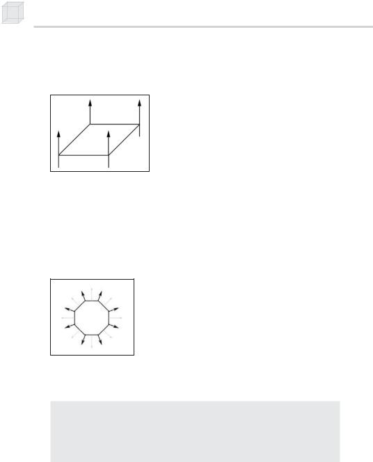
Vertex normals are based on the same idea, but rather than specifying the normal per polygon, we specify them for each vertex that forms the polygon (see Figure 5.2).
Figure 5.2: The vertex normals of a surface
Direct3D needs to know the vertex normals so that it can determine the angle at which light strikes a surface, and since lighting calculations are done per vertex, Direct3D needs to know the surface orientation (normal) per vertex. Note that the vertex normal isn’t necessarily the same as the face normal. Sphere/circle approximations are good examples of objects where the vertex normals are not the same as the triangle normals (see Figure 5.3).
Figure 5.3: An example where vertex normals are different from the face normal. The bolder vectors denote the vertex normals, while the lighter vectors denote the face normals.
To describe the vertex normal of a vertex, we must update our vertex structure:
struct Vertex
{
float _x, _y, _z; float _nx, _ny, _nz; static const DWORD FVF;
}
const DWORD Vertex::FVF = D3DFVF_XYZ | D3DFVF_NORMAL;
Notice that we have removed the color member that was used in the last chapter. This is because we are using lighting to compute the colors of our vertices.
For simple objects such as cubes and spheres, we can see the vertex normals by inspection. For more complex meshes, we need a more mechanical method. Suppose a triangle is formed by the vertices p0, p1,

Lighting 103
and p2, and we need to compute the vertex normal for each of the verti-
ces n0, n1, and n2.
The simplest approach, and the approach we illustrate, is to find the face normal of the triangle that the three vertices form and use the face normal as the vertex normals. First compute two vectors that lie on the triangle:
p1 p0 u p2 p0 v
Then the face normal is: n u v
Since each vertex normal is the same as the face normal:
n0 n1 n2 n
Below is a C function that computes the face normal of a triangle from three vertex points on the triangle. Note that this function assumes that the vertices are specified in a clockwise winding order. If they are not, the normal will point in the opposite direction.
void ComputeNormal(D3DXVECTOR3* p0, D3DXVECTOR3* p1, D3DXVECTOR3* p2, D3DXVECTOR3* out)
{
D3DXVECTOR3 u = *p1 - *p0; D3DXVECTOR3 v = *p2 - *p0;
D3DXVec3Cross(out, &u, &v); D3DXVec3Normalize(out, out);
}
Using face normals as vertex normals does not produce smooth results when approximating curved surfaces with triangles. A better method for finding a vertex normal is normal averaging. To find the vertex normal vn of a vertex v, we find the face normals for all the triangles in the mesh that share vertex v. Then vn is given by averaging all of these face normals. Here’s an example to illustrate. Suppose three triangles, whose face normals are given by n0, n1, and n2, share the vertex v. Then vn is given by averaging the face normals:
vn 1 n0 n1 n2
3
P a r t I I
During the transformation stages, it is possible for vertex normals to become non-normal. Therefore, it is best to be safe and have Direct3D