

Introduction to 3D Game Programming with DirectX.9.0 - F. D. Luna
.pdf164 Chapter 10
Flags—Optimization flags that tell the method what kind of optimizations to perform. These can be one or more of the following:
D3DXMESHOPT_COMPACT—Removes unused indices and vertices from the mesh
D3DXMESHOPT_ATTRSORT—Sorts the triangles by attribute
|
and generates an attribute table. This allows DrawSubset to |
|
|
|
Y |
|
be more efficient (see section 10.5). |
|
|
|
L |
|
D3DXMESHOPT_VERTEXCACHE—Increases vertex cache rate |
|
|
hits |
|
D3DXMESHOPT_STRIPREORDER—Reorganizes the indices so
D3DXMESHOPT IGNOREVERTS—Optimizes index info only; |
|
EA |
|
ignore vertices |
F |
that triangle stripsMcan be as long as possible
Note: The D3DXM SHOPT V RTEXC CHE and D3DXMESHOPT_
STRIPREORDER flags cannot be used together.
pAdjacencyIn—Pointer to the adjacency array of the non-optimized mesh
pAdjacencyOut—Pointer to a DWORD array to be filled with the adjacency info of the optimized mesh. The array must have
ID3DXMesh::GetNumFaces() * 3 elements. If you do not need this info, pass 0.
pFaceRemap—Pointer to a DWORD array to be filled with the face remap info. The array should be of size ID3DXMesh::GetNumFaces(). When a mesh is optimized, its faces may be moved around in the index buffer. The face remap info tells where the original faces have moved to; that is, the ith entry in pFaceRemap holds the face index identifying where the ith original face has moved. If you do not need this info, pass 0.
ppVertexRemap—Address of a pointer to an ID3DXBuffer (see section 11.1) that will be filled with the vertex remap info. This buffer should contain ID3DXMesh::GetNumVertices() vertices. When a mesh is optimized, its vertices may be moved around in the vertex buffer. The vertex remap info tells where the original vertices have moved; that is, the ith entry in ppVertexRemap
holds the vertex index identifying where the ith original vertex has moved. If you do not need this info, pass 0.T
Team-Fly®

Meshes Part I 165
Example call:
//Get the adjacency info of the non-optimized mesh. DWORD adjacencyInfo[Mesh->GetNumFaces() * 3]; Mesh->GenerateAdjacency(0.0f, adjacencyInfo);
//Array to hold optimized adjacency info.
DWORD optimizedAdjacencyInfo[Mesh->GetNumFaces() * 3];
Mesh->OptimizeInplace( D3DXMESHOPT_ATTRSORT | D3DXMESHOPT_COMPACT | D3DXMESHOPT_VERTEXCACHE, adjacencyInfo, optimizedAdjacencyInfo, 0, 0);
A similar method is the Optimize method, which outputs an optimized version of the calling mesh object rather than actually optimizing the calling mesh object.
HRESULT ID3DXMesh::Optimize(
DWORD Flags,
CONST DWORD* pAdjacencyIn,
DWORD* pAdjacencyOut,
DWORD* pFaceRemap, LPD3DXBUFFER* ppVertexRemap,
LPD3DXMESH* ppOptMesh // the optimized mesh to be output
);
10.5 The Attribute Table
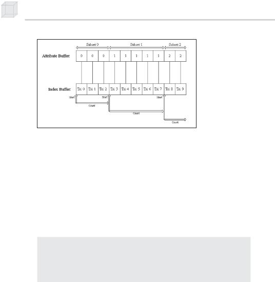
When a mesh is optimized with the D3DXMESHOPT_ATTRSORT flag, the geometry of the mesh is sorted by its attribute so that the geometry of a particular subset exists as a contiguous block in the vertex/index buffers (see Figure 10.3).
P a r t I I I
166 Chapter 10
Figure 10.3: Notice that the geometry and attribute buffer are sorted by attribute such that the geometry of a particular subset is contiguous. We can now easily mark where the geometry of one subset begins and ends. Note that every “Tri” block in the index buffer represents three indices.
In addition to sorting the geometry, the D3DXMESHOPT_ATTRSORT optimization builds an attribute table. The attribute table is an array of D3DXATTRIBUTERANGE structures. Each entry in the attribute table corresponds to a subset of the mesh and specifies the block of memory in the vertex/index buffers, where the geometry for the subset resides. The D3DXATTRIBUTERANGE structure is defined as:
typedef struct _D3DXATTRIBUTERANGE { DWORD AttribId;
DWORD FaceStart;
DWORD FaceCount;
DWORD VertexStart;
DWORD VertexCount; } D3DXATTRIBUTERANGE;
AttribId—The subset ID
FaceStart—An offset into the index buffer (FaceStart * 3) identifying the start of the triangles that are associated with this subset
FaceCount—The number of faces (triangles) in this subset
VertexStart—An offset into the vertex buffer identifying the start of the vertices that are associated with this subset.
VertexCount—The number of vertices in this subset
We can easily see the members of the D3DXATTRIBUTERANGE structure at work graphically in Figure 10.3. The attribute table for the mesh in Figure 10.3 would have three entries—one to correspond with each subset.

Meshes Part I 167
With the attribute table built, rendering a subset can be done very efficiently, for only a quick lookup in the attribute table is required to find all the geometry of a particular subset. Note that without an attribute table, rendering a subset requires a linear search of the entire attribute buffer to find the geometry that exists in the particular subset that we are drawing.
To access the attribute table of a mesh, we use the following method:
HRESULT ID3DXMesh::GetAttributeTable(
D3DXATTRIBUTERANGE* pAttribTable,
DWORD* pAttribTableSize
);
This method can do two things: It can return the number of attributes in the attribute table or it can fill an array of D3DXATTRIBUTERANGE structures with the attribute data.
To get the number of elements in the attribute table, we pass in 0 for the first argument:
DWORD numSubsets = 0;
Mesh->GetAttributeTable(0, &numSubsets);
Once we know the number of elements, we can fill a D3DXATTRIBUTERANGE array with the actual attribute table by writing:
D3DXATTRIBUTERANGE table = new D3DXATTRIBUTERANGE [numSubsets];
Mesh->GetAttributeTable( table, &numSubsets );
We can directly set the attribute table using the ID3DXMesh::SetAttributeTable method. The following example sets an attribute table with 12 subsets:
D3DXATTRIBUTERANGE attributeTable[12];
// ...fill attributeTable array with data
Mesh->SetAttributeTable( attributeTable, 12);
10.6 Adjacency Info
For certain mesh operations, such as optimizing, it is necessary to know the triangles that are adjacent to a given triangle. A mesh’s adjacency array stores this information.
The adjacency array is a DWORD array, where each entry contains an index identifying a triangle in the mesh. For example, an entry i refers to the triangle formed by indices:
P a r t I I I

168 Chapter 10
A= i 3
B= i 3 + 1
C= i 3 + 2
Note that an entry of ULONG_MAX = 4294967295 as its value indicates that the particular edge does not have an adjacent triangle. We can also use –1 to denote this because assigning –1 to a DWORD results in ULONG_MAX. To see this, recall that a DWORD is an unsigned 32-bit integer.
Since each triangle has three edges, it can have up to three adjacent triangles (see Figure 10.4).
Figure 10.4: We see that each triangle has three entries in the adjacency array that identify the triangles adjacent to it. For instance, Tri: 1 has two adjacent triangles (Tri: 0 and Tri: 2). Thus for Tri: 1 there is a 0, 2, and –1 in its corresponding adjacency entries specifying that Tri: 0 and Tri: 2 are adjacent. The –1 indicates that one edge of Tri: 1 doesn’t have an adjacent triangle.
Therefore, the adjacency array must have (ID3DXBaseMesh::GetNumFaces() * 3) elements—three possible adjacent triangles for every triangle in the mesh.
Many of the D3DX mesh creation functions can output the adjacency info, but the following method can also be used:
HRESULT ID3DXMesh::GenerateAdjacency(
FLOAT fEpsilon,
DWORD* pAdjacency
);
fEpsilon—An epsilon value specifying when two points are close enough in distance that they should be treated as the same. For instance, if the distance between two points is less than epsilon, we treat them as the same.
pAdjacency—A pointer to an array of DWORDs that is to be filled with the adjacency info

Meshes Part I 169
Example:
DWORD adjacencyInfo[Mesh->GetNumFaces() * 3];
Mesh->GenerateAdjacency(0.001f, adjacencyInfo);
10.7 Cloning
Sometimes we need to copy the data from one mesh to another. This is accomplished with the ID3DXBaseMesh::CloneMeshFVF method.
HRESULT ID3DXMesh::CloneMeshFVF(
DWORD Options,
DWORD FVF,
LPDIRECT3DDEVICE9 pDevice,
LPD3DXMESH* ppCloneMesh
); |
|
|
|
Options—One or more creation flags that are used to create the |
|
||
cloned mesh. See the D3DXMESH enumerated type in the SDK doc- |
|
||
umentation for a complete list of option flags. Some common flags |
|
||
are: |
|
|
|
D3DXMESH_32BIT—The mesh will use 32-bit indices. |
|
||
D3DXMESH_MANAGED—The mesh will be placed in the man- |
|
||
aged memory pool. |
|
|
|
D3DXMESH_WRITEONLY—The mesh’s data will only be writ- |
|
||
ten to and not read from. |
|
|
|
D3DXMESH_DYNAMIC—The mesh’s buffers will be made |
|
||
III |
|||
dynamic. |
|
||
FVF—The flexible vertex format with which to create the cloned |
rt |
||
mesh |
|
Pa |
|
pDevice—The device to be associated with the cloned mesh |
|
||
|
|||
ppCloneMesh—Outputs the cloned mesh |
|
||
Notice that this method allows the creation options and flexible vertex |
|
||
format of the destination mesh to be different from those of the source |
|
||
mesh. For example, suppose we have a mesh that has the flexible ver- |
|
||
tex format D3DFVF_XYZ and we would like to create a clone but with a |
|
||
vertex format of D3DFVF_XYZ | D3DFVF_NORMAL. We would write: |
|
||
// assume _mesh and device are valid |
|
||
ID3DXMesh* clone = 0; |
|
|
|
Mesh->CloneMeshFVF( |
|
|
|
Mesh->GetOptions(), |
// use same options as source mesh |
|
|
D3DFVF_XYZ | D3DFVF_NORMAL,// specify clones FVF Device,
&clone);

170Chapter 10
10.8Creating a Mesh (D3DXCreateMeshFVF)
Thus far, we have created mesh objects using the D3DXCreate* functions. However, we can also create an “empty” mesh using the D3DXCreateMeshFVF function. By empty mesh, we mean that we specify the number of faces and vertices that we want the mesh to be able to hold; then D3DXCreateMeshFVF allocates the appropriately sized vertex, index, and attribute buffers. Once we have the mesh’s buffers allocated, we manually fill in the mesh’s data contents (that is, we must write the vertices, indices, and attributes to the vertex buffer, index buffer, and attribute buffer, respectively).
As said, to create an empty mesh we use the D3DXCreateMeshFVF function:
HRESULT D3DXCreateMeshFVF(
DWORD NumFaces,
DWORD NumVertices,
DWORD Options,
DWORD FVF, LPDIRECT3DDEVICE9 pDevice, LPD3DXMESH* ppMesh
);
NumFaces—The number of faces the mesh will have. This must be greater than zero.
NumVertices—The number of vertices the mesh will have. This must be greater than zero.
Options—One or more creation flags that will be used to create the mesh. See the D3DXMESH enumerated type in the SDK documentation for a complete list of option flags. Some common flags are:
D3DXMESH_32BIT—The mesh will use 32-bit indices.
D3DXMESH_MANAGED—The mesh will be placed in the managed memory pool.
D3DXMESH_WRITEONLY—The mesh’s data will only be written to and not read from.
D3DXMESH_DYNAMIC—The mesh’s buffers will be made dynamic.
FVF—The flexible vertex format of the vertices stored in this mesh
pDevice—The device associated with the mesh
ppMesh—Outputs the created mesh

Meshes Part I 171
The sample application, reviewed in the next section, gives a concrete example of how to create a mesh using this function and manually fill in the mesh’s data contents.
Alternatively, you can create an empty mesh with the D3DXCreateMesh function. Its prototype is:
HRESULT D3DXCreateMesh(
DWORD NumFaces,
DWORD NumVertices,
DWORD Options,
CONST LPD3DVERTEXELEMENT9* pDeclaration, LPDIRECT3DDEVICE9 pDevice,
LPD3DXMESH* ppMesh
);
The parameters are similar to D3DXCreateMeshFVF, except for the fourth. Instead of specifying the FVF, we specify an array of D3DVERTEXELEMENT9 structures that describe the format of the vertices. For now, we leave it to the reader to investigate the D3DVERTEXELEMENT9 structure; however, the following related function is worth mentioning:
HRESULT D3DXDeclaratorFromFVF(
DWORD FVF, // input format
D3DVERTEXELEMENT9 Declaration[MAX_FVF_DECL_SIZE]//output format
);
 Note: D3DVERTEXELEMENT9 is discussed in Chapter 17.
This function outputs an array of D3DVERTEXELEMENT9 structures given an FVF as input. Note that MAX_FVF_DECL_SIZE is defined as:
typedef enum { MAX_FVF_DECL_SIZE = 18
} MAX_FVF_DECL_SIZE;
10.9 Sample Application:
Creating and Rendering a Mesh
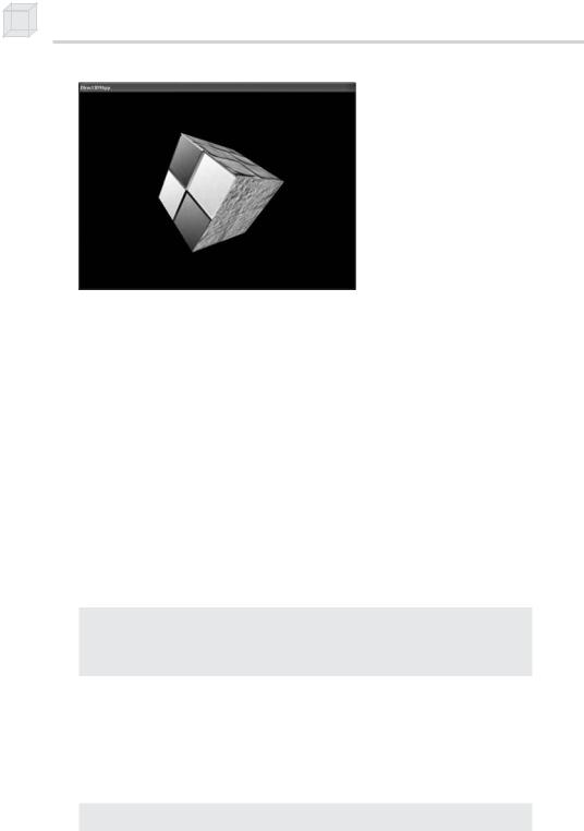
The sample application for this chapter renders a mesh of a box (see Figure 10.5).
P a r t I I I
172 Chapter 10
Figure 10.5: Screen shot of a cube created and rendered as an ID3DXMesh object
It demonstrates most of the functionality that we have discussed in this chapter, including the following operations:
Creating an empty mesh
Filling the mesh with the geometry of a cube
Specifying the subset in which each face of the mesh exists
Generating the adjacency info of the mesh
Optimizing the mesh
Drawing the mesh
Note that we omit irrelevant code from the discussion of the sample. You can find the complete source code in the companion files. This sample is called D3DXCreateMeshFVF.
In addition, to facilitate debugging and investigating the components of a mesh, we implement the following functions that dump its internal contents to file:
void dumpVertices(std::ofstream& outFile, ID3DXMesh* mesh); void dumpIndices(std::ofstream& outFile, ID3DXMesh* mesh);
void dumpAttributeBuffer(std::ofstream& outFile, ID3DXMesh* mesh); void dumpAdjacencyBuffer(std::ofstream& outFile, ID3DXMesh* mesh); void dumpAttributeTable(std::ofstream& outFile, ID3DXMesh* mesh);
The names of these functions describe their actions. Since the implementations of these functions are straightforward, we omit a discussion of them here (see the source code in the companion files). However, we do show an example of dumpAttributeTable later in this section.
To begin our review of the sample, we instantiate the following global variables:
ID3DXMesh* |
Mesh = 0; |
const DWORD |
NumSubsets = 3; |

Meshes Part I 173
IDirect3DTexture9* Textures[3] = {0, 0, 0};// texture for each subset
std::ofstream OutFile; // used to dump mesh data to file
Here we have instantiated a pointer to a mesh that we create later. We also define the number of subsets that the mesh will have—three. In this example, each subset is rendered with a different texture; the array Textures contains a texture for each subset, such that the ith index in the texture array is associated with the ith subset of the mesh. Finally, the variable OutFile is used to output the contents of the mesh to a text file. We pass this object to the dump* functions.
The majority of the work for this sample takes place in the Setup function. We first create an empty mesh:
bool Setup()
{
HRESULT hr = 0;
hr = D3DXCreateMeshFVF( 12, 24,
D3DXMESH_MANAGED, Vertex::FVF, Device,
&Mesh);
Here we allocate a mesh with 12 faces and 24 vertices, the amount needed to describe a box.
At this point, the mesh is empty, so we need to write the vertices and indices that describe a box to the vertex buffer and index buffer, respectively. Locking the vertex/index buffer and manually writing the data easily accomplishes this:
//Fill in vertices of a box Vertex* v = 0;
Mesh->LockVertexBuffer(0, (void**)&v);
//fill in the front face vertex data
v[0] = Vertex(-1.0f, -1.0f, -1.0f, 0.0f, 0.0f, -1.0f, 0.0f, 0.0f); v[1] = Vertex(-1.0f, 1.0f, -1.0f, 0.0f, 0.0f, -1.0f, 0.0f, 1.0f);
.
.
.
v[22] = Vertex( 1.0f, 1.0f, 1.0f, 1.0f, 0.0f, 0.0f, 1.0f, 1.0f); v[23] = Vertex( 1.0f, -1.0f, 1.0f, 1.0f, 0.0f, 0.0f, 1.0f, 0.0f);
P a r t I I I
Mesh->UnlockVertexBuffer();