

Ceramic Technology and Processing, King
.pdfFiring 293
Figure 8.29: Hot Press, Induction. The induction coil heats the susceptor that in turn heats the hot pressing mold.
The ram is part of the hydraulic press. For lab work, a 50-ton press is suitable. When money is scarce, an inexpensive H-frame, hand-pumped press works well. An induced electrical circuit is made through the press frame retrofitted with insulated bolts and sleeves. Refractory blocks are for thermal insulation. Zirconia refractory has low thermal conductivity and is useful for this purpose.
Graphite cylinders transmit the force to the graphite mold. These will oxidize; it is a good idea to include a sleeve for protection. Graphite is machined into a tube for the susceptor. Additionally, thermally insulate the tube with graphite felt or bubble zirconia for use to about 1750 °C. The shell must be an electrical insulator with fiber reinforced cement tubing. Induction coils are copper tubing with circulating water for cooling. Separate the coils with insulated spacers. Match the number of coils to the

294 Ceramic Technology and Processing
power supply. The base plate is also insulating and can be a reinforced cement material or refractory. Graphite molds will be discussed further.
Resistance Heating
Many commercial hot presses use a resistance element for heating. One can also use carbon tube furnaces. Figure 8.30 illustrates such a hot press.
Figure 8.30: Hot Press, Resistance. A tubular heating element is used to heat the mold compressed through end seals with a hydraulic ram.
Firing 295
In this design, the mold is smaller than the heating element. It is easy to separate the mold electrically by wrapping a pressure sensitive adhesive paper tape (masking tape) around the mold on both ends. Then, place it in the press, putting on the end seals that have the bellows, and apply a little pressure. When the paper chars off, suspend the mold away from the heating element. Graphite fiber blanket is the preferred thermal insulation as it is less messy than tamped lamp black.
Optical pyrometers are usually used for temperature measurement. Control the thermal cycle manually or automatically. Due to the short cycles, manual control is perhaps preferable.
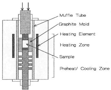
Insulated leads (not shown) bring in the electrical connections. A very useful laboratory hot press is one that can be preheated with subsequent mold insertion into the hot zone. This greatly reduces the heating-up time. After pressing, one can withdraw the mold into a cooling chamber. This is shown in Figure 8.31.
Figure 8.31: Hot Press, Insertion. The hot press is preheated followed by the mold insertion.
296 Ceramic Technology and Processing
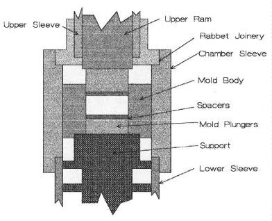
Preheat the hot press to or a little above the soak temperature. Then, insert the mold assembly part way into the furnace for preheating just below the temperature that causes the sample to shrink. If it does shrink and pulls away from the walls, the run will be a failure as the sample will fracture and will not reheal. Next, lift the mold into the hot zone and apply pressure. A dial micrometer on the press ram will indicate when shrinkage is complete, which could be as soon as five minutes. Following this, lower the mold below the preheating zone for cooling. Once the mold temperature is below 800 °C, remove the mold, with the total time of about 20 minutes. With this procedure, one can approach the isothermal conditions for hot pressing and can also approximate the densification kinetics. Figure 8.31 does not have some detail of the mold assembly because of the scale. Figure 8.32 shows these details.
Figure 8.32: Mold Assembly Detail. The mold assembly is joined so that it stays in alignment.
Firing 297
The assembly is supported on the Lower Sleeve, which holds the Chamber Sleeve in place. The Upper Sleeve extends to the top where it is secured, water cooled, and sealed with metal bellows. There is a shoulder (not shown) on the Upper Ram to prevent it from dropping out the bottom of the furnace. To load the furnace, the Support, Mold with Spacers, and Plungers are pushed up into the furnace to the desired location for preheating and held there with blocks. The bottom is also water cooled with a copper coil. This furnace was induction heated, also not shown.
Vacuum Hot Presses
As mentioned before, these are essentially vacuum furnaces with the means to introduce a ram for pressing. A metal bellow is a good choice as elastomeric seals wear out. These can be resistance or induction heated and can be heated with metal or graphite heating elements. There are two advantages of vacuum hot presses. One can purge the system, hot press the sample in a relatively pure gas, and process the sample in a vacuum. However, the mold is graphite that can react with the material being hot pressed.
Hot Pressing Molds
Almost all molds are machined from a billet of graphite. ATJ is a finegrained graphite with good uniformity and strength. Tensile strength increases with temperature from 2200 psi at room temperature to 4000 psi at 2400 °C. Since graphite is highly anisotropic, thermal expansion varies with orientation, being 2.34x10⁻⁶/ °C with the grain and 3.46x10⁻⁶/ °C across the grain for ATJ. These are low expansions compared with most ceramics, which is fortunate or the hot-pressed part would place the mold in tension when cooled.
Monolithic Molds. Lab molds are usually right circular cylinders with two end plungers. Parts needed for testing are machined from the hot-pressed disc. Parts with an aspect ratio of up to 10:1 can be hot pressed in
298 Ceramic Technology and Processing
monolithic molds. The furnace ID, maximum size of ATJ graphite that is a block 9"x20"x24", and the hydraulic press dictate the maximum diameter.
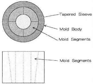
Segmented molds. These have advantages of disassembly. An example is shown in Figure 8.33.
Figure 8.33: Split Mold Design. The interior of a hot-pressing mold can consist of segments that can be pressed out as a unit.
With the segments on a taper, one can easily push out the segments and the part out of the mold and lift the part off. Ordinarily, one can strip the part from the mold, leaving score marks on the ID. These get worse with each run as the interior becomes progressively damaged. With a split mold, the damage is much less, occurring only during pressing. Split molds have another advantage. When the part bonds to the graphite only the
Firing 299
segments are sacrificed and the part is more easily recovered. A thin sleeve of graphite, graphite foil, or Mo foil can line the ID, preserving the segments. A split mold is more expensive due to the extra machining, but this is not a big factor in lab work, and the mold body can accommodate a variety of segment ID configurations. The following Table 8.1 lists a few thermal expansions of common materials.
Table 8.1: Thermal Expansion of Common Materials
Material |
Thermal Expansion % to 1000 |
|
°C |
|
|
SiO2 ,glass |
0.055 |
|
|
Si3N4, (beta) |
0.22 |
|
|
Graphite,ATJ |
0.23 with grain, 0.35 across grain |
|
|
Si3N4 (alpha) |
0.28 |
|
|
WC |
0.48 |
|
|
SiC |
0.5 |
|
|
B4C |
0.54 |
|
|
ZrO2 (monoclinic) |
0.74 |
|
|
TiC |
0.75 |
|
|
Al2O3 (alpha) |
0.83 |
|
|
Material |
Thermal Expansion % to 1000 °C |
|
|
MoSi2 |
0.83 |
|
|
BN |
1.3 (anisotropic) |
|
|
MgO |
1.33 |
|
|
300 Ceramic Technology and Processing
Any material with a lower thermal expansion than graphite will jam in the mold as it cools. Since the part will shrink less than the graphite, there will be an interference fit on the interface, placing the part in compression and the mold in tension. Fortunately, there are not many materials with this low an expansion. As one approaches the expansion of graphite, one can expect greater difficulty in stripping the part. The split mold bypasses this problem.
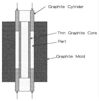
Hot Pressing Tubes. The preceding conclusions on thermal expansion referred to the stresses on the ID of the mold, but what if the intention is to hot press a tube? In this case, the ID of the part is in tension and the OD of the central graphite form is in compression. The part will break for sure. Figure 8.34 represents a partial solution.
Figure 8.34: Mold for Tubular Shape. The central tube has to be thin enough so that the part does not fracture in tension during cooling.
Firing 301
The central graphite core must be thin walled in order for it to yield or collapse during cooling. If it is too thin, the wall will collapse during hot pressing, so it has to be just right. This might take a few trials. Aspect ratios are about the same for tubes as for cylinders, but the pressure has to be limited, especially at first. When the plungers start to move, the material in the mold is deformable to some extent, and the graphite gets a little stronger. One can now gradually increase the pressure.
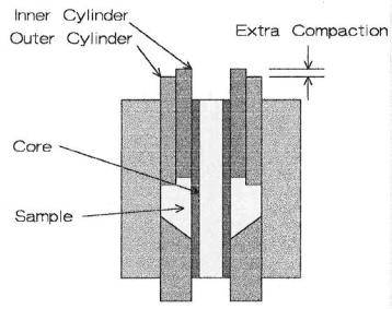
Cones. One can hot press conical shapes as the sintering ceramic has some capacity for lateral movement. Not much, but some. Figure 8.35 sketches a mold where the top plunger is in two parts to compensate for the longer vertical movement of the thicker section.
Figure 8.35: Mold for Conical Shape. Due to the large difference in height, an extra pressing ring may be needed to obtain full densification in the center.
302 Ceramic Technology and Processing
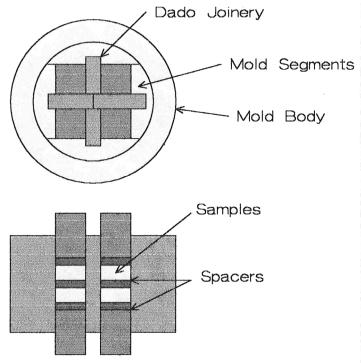
Reactions with the Graphite. Materials that require a high temperature to densify will react with the mold and will tend to stick. This is especially true with carbides, borides, and nitrides. In the worst case, it may only be possible to recover the part by sand blasting the mold. Sleeved segmented molds are useful here if the temperature is low enough for Mo foil (about 1700 °C). Graphite spacers and liners can simplify recovery of the part. A mold of this type is sketched in Figure 8.36.
Figure 8.36: Mold with Spacers and Liners. A multiplicity of cavities can be made with spacers and dividers.
This mold hot presses eight pieces per run. Position the graphite dividers with dado joinery. The entire core assembly is pushed out and the