

Ceramic Technology and Processing, King
.pdfForming 203
equipment, and particle segregation. Segregation is a serious problem even with fine-grained slips. This can be approached by flocculating the slip. This is a good approach, but there still are segregation problems.
A centrifuge was used in some experiments in our lab. A plaster base was cast to absorb the water in the slip. After drying the plaster, the slip was poured into the centrifuge tube and was centrifugally cast. Casting was fast due to the high g forces. It took longer to get the centrifuge up to the required speed and then down again than it took the slip to cast. The centrifuge had a fixed rotor as seen in Figure 6.44.
Figure 6.44: Centrifically Casting Experimental Apparatus
Due to the rotor geometry, the casting was on a slant as seen in Figure 6.44. The material is a slip containing an alumina powder with a d50 of 0.6 μm. It is segregated with fine material on top, which cracked on drying. In these particular tests, flocculation of the particles did not alleviate the segregation problem. In retrospect, a high speed centrifuge at 10 to 20,000 g was used. One should try a lower speed to prevent crushing the soft floccs,.
204 Ceramic Technology and Processing
Gel Casting
One gel casting process is based on a polymer/solvent system with a catalyst to kick off the reaction.12 Gel casting goes back in time in ceramics with cements, castables, zirconylchloride gels, alginate gels, and a variety of other systems.
Viscosity of fine-grained slips increases rapidly above about 50 volume % solids. To have a fluid slip, the solid's content is usually about 45%. Volume % solids and fine-particle size exacerbate the problems of drying and firing shrinkages, leading to distortions, cracking, and geometrical part limitations. Recently, considerable progress has been made despite these problems.
Complex parts have been cast with this process. When working with this technology, look for drying and cracking problems. The difficulties are inherent with fine-grained slips, but these are tractable. One approach to alleviating problems is by adding some coarser (4-5 μm) particles to the slip, thus increasing the solid content.
When the material is coarse grained with a variety of finer sizes, the permeability and the solid's volume % are both higher and drying problems are much less troublesome. Cements and castables avoid some difficulties with gels in that they are heavily loaded with ceramic particles that minimize drying shrinkage. While these do use a gelation process, they are not generally thought of as gel casting. The cementatious phase is calcium aluminate that hydrates and gels. Upon firing, the phase crystallizes. Calcium aluminate is a refractory material in its own right and is suitable as a bond in refractories. Additives are available for either shortening or lengthening the set time. A few grades are commercially available.
An alginate derivative with the trade name Superloid has been used for gel casting. A slip containing 1% or 2% Superloid will gel when immersed in a calcium chloride solution. Drying problems limit the size of parts made in this way. The high viscosity of the Superloid solution causes relatively low solids content in the slip and the parts will not have high strengths. Also, non-leachable Ca ++ remains in the body, changing its chemistry.
Forming 205
Injection Molding
Conventional injection molding uses either a wax or a polymer melted to impart fluidity. Complex shapes can be made by injection molding, often making this technique the preferred process. Lots of ceramic parts are injection molded, attesting to the usefulness of the process. This subject is voluminous, complex, and beyond the scope of this book.
A few comments appropriately point out some differences between polymer injection molding and injection molding of ceramics.
Polymer molding has additives that impart particular properties to the molded part. These can be fillers, antioxidants, opacifers, flame retardants, and pigments. These materials are added at relatively low percentages as compared to ceramic formulations. Ceramic injection molding is distinctly different because the polymer or wax is fugitive and only assists in forming. This makes for a substantial difference in formulation. Ceramic mixes are much heavier loaded, usually around 4550% solids by volume. This leads to a different set of problems. Ceramic particles can segregate in mixing and in transport during processing. Design of the apparatus, molds, and procedures have their own criteria. Conditions in the die cavity are not uniform principally because of pressure and temperature gradients. When this leads to density gradients in the green ceramic, the part will distort or crack during firing. Data on strength is usually lower than that from other forming processes. An additional problem is binder burnout. Polymers swell upon heating and the part is about half polymers by volume. Polymers also create voluminous gas, during burnout, that require slow and controlled firing schedules. Since burnout involves reheating the part, it can slump as the binder softens. Large parts are saggered and supported by an adsorbent pack during burnout, introducing a separate step in the process. We have to keep in mind that ceramic parts are being made every day by injection molding so these problems are not intractable.
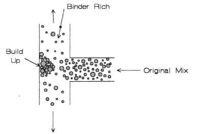
There is a very interesting paper that reveals segregation of phases during powder injection molding, largely due to design of the runners and gates.13 Wherever there is a sharp turn or nook, the powder particles tend to pack to a higher volume % as in Figure 6.45.
206 Ceramic Technology and Processing
Figure 6.45: Solids pile up on a junction during powder injection molding.
The illustration could have as well been of a sharp corner. The consequence is that the mix is being segregated into high and low volume fractions of solids, which will remain after the binder is burned out. One example is where the location of the gate in a fired part has small cracks, probably because this was a solids-deficient area in the molding. The author of this paper illustrated the proper way to design dies for powder injection molding, as is redrawn schematically in Figure 6.46. The design avoids corners where segregation takes place.

Forming 207
Figure 6.46: Runner design to prevent pile up of particles during powder injection molding.
Adiabatic Molding of Ceramics
So far, experimental processes have not been included in this text, except for one gel casting method. Adiabatic molding is an experimental process.14 It is included because it has attributes that may offer some advantages.
This process is a water-based system. Water is an unusual material in that the liquid has a higher density than the solid. Because ice floats, pressure, rather than temperature, can be used to melt ice. This requires an explanation. Figure 6.47 is the phase diagram of water.15
In the example, at -10 °C at point A, when the pressure is increased to about 180 MPa at point B, the liquidus is crossed and the ice melts. The conclusion being that pressure can be used to melt ice instead of the usual way for melting by raising the temperature. Consider an example. Alumina with a median particle size of 0.6 μm can be mixed by hand with a 3%

208 Ceramic Technology and Processing
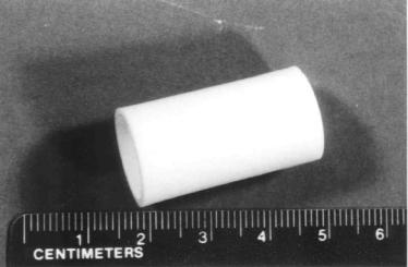
PVA solution to make a dough. A pellet of this dough is placed in a die and put into a freezer. The die is configured to a crucible shape. Overnight, the assembly is equilibrated at -10 °C. As pressure is applied to the pellet the next day, the water in the pellet is melted and the mix then is injected into the die. When the pressure is released, the water solidifies and the part can be ejected from the mold. Dried and fired the crucible shape is produced.
Figure 6.47: Phase Diagram, Water. Liquid water can be present above the triple point. Water frozen at (A) will melt when pressurized to point (B).
Figure 6.48 is an alumina crucible shape with the dimensions; 16 mm OD, 14 mm ID, 30 mm long, and 21 mm deep inside. This is not an easy part to make by other methods as it has a 1mm wall over a 9 mm thick base.
The process works as expected with pressure being effective to melt and then freezing the mix, but there is a problem. When the pressure is released, the water freezes and expands. Since this is a cylindrical mold, the part was free to expand only along the axial direction. This results in
Forming 209
shear within the piece, resulting in shear cracking. The problem is not intractable as articulated tooling could provide the space necessary for the part to expand freely when the pressure is released. This is speculative now as this could be a little tricky. Internal pressure and temperature in the die are uniform after the dough has been injected. Therefore, mix viscosity is uniform throughout the die cavity. In turn, packing is uniform avoiding some problems inherent in conventional injection molding. Another good feature is that the dough is mixed at room temperature. This results in a useful process simplification.
Figure 6.48: Adiabatic Molded Crucible. The shape has a large discrepancy between wall thickness and base thickness.
Check List, Other Casting Procedures
•Pressure casting: fast cast, thick walls, reduce settling, safety valve
•T casting: coarse slips, high solids, timing
•Centrifugal casting: segregation, flocculate slip
210Ceramic Technology and Processing
•Gel casting: warping, cracking, coarsen slip, high solids
•Injection molding: density gradients, low solids content, expensive tooling for a lab process, preventing segregation of solids by design.
•Adiabatic molding: experimental, uniform high density, expensive articulated tooling for a lab process
8.0 EXTRUSION
Equipment for extrusion was described in Chapter V. Extrusion is a common forming method for making cylindrical shapes. A cylinder is being used in its broader sense, where it is any three-dimensional form consisting of parallel straight lines. The cross section can be square, rectangular, oval, a star, or a honeycomb, to name a few cylinders. Common extrusions are bricks, tubes, solid cylinders, mill lining blocks, and honeycombs used as heat exchangers and automobile exhaust catalyst supports.
Preparation of the mix was described in Chapter V. It has to be plastic like stiff mud. It is usually flocculated. Clay bodies are naturally plastic especially when they contain ball clay. A small amount of clay or other alumina silicate such as Hectorite can be added to oxides or carbides to increase fluidity. Organic, long-chain polymers or alginates can also be added to increase fluidity.
The extrusion is run out of the die onto a table and wire cut to length. When the extruder is vertical, it is run out onto a board, cut, and swung away horizontally. In both cases, the idea is to keep the extrusion straight. If it is bent, the particles on the compression side will be compacted, while those on the tensile side will be extended. Subsequently, the part will warp when fired even if it is straightened back out. Common practice is to use V blocks to keep rods and tubes straight as they dry.
There are many variations on extrusion; two are briefly described
below.
Honeycombed. The extrusion mix in one instance contained methyl cellulose.16 This material is unusual as a water solution of it
Forming 211
becomes more viscous when heated. To preserve the shape and keep it from sagging, the extrusion die is heated causing the shape to stiffen.
End Flange. A plate with a cavity can be placed on the extrusion die, forming a flange on the end of the piece. The plate is then removed and the length extruded.
9.0 DRYING PARTS
Green ceramic parts are dried after forming, provided of course that a liquid is present. Drying increases the green strength and readies the part for sintering. When the interstitial phase is a polymer or wax, such as in injection molding, the removal process is called burnout.
Drying Conditions
Conditions of the body that are important are thermal conductivity, permeability, and drying shrinkage.
Conditions in the dryer that are important are temperature and relative humidity.
Before these are discussed, consider what happens as a part is dried. Depending on particle packing, most parts will shrink when dried. The outside shrinks first. Since it is restrained from shrinking by the interior, it may crack as shown in Figure 6.49.
This is particularly troublesome when the part is thick and the interior may not even be warm. The problem then is to program drying so that differential shrinkage between the surface and interior does not exceed the tensile strength of the material.
In extreme cases, internal pressure can burst the part when the water vapor is being generated faster than it can diffuse out of the body. Fine-grained, dense bodies are susceptible to bursting when dried too fast.

212 Ceramic Technology and Processing
Figure 6.49: Drying Shrinkage. Uneven shrinkage can result in cracking.
Permeability
Water evaporates during drying and has to escape from the interior of the article. Remember that one mole of water (18 g) will create 22.4 liters of steam at STP. Since it is hot, there is even a greater volume of gas that has to escape. When permeability is low, internal pressures can build up and burst the part. Fine-grained ceramics have low permeability and have to be dried slowly. Laboratory practices are not especially urgent so a relatively low temperature, say 60 °C, is about right. A flow of air in the oven helps to remove the water vapor from the oven. Keep the vent open. Coarse-grained bodies have higher permeability and are not always thoroughly dried as they can dry in the initial ramp of the firing curve.
Setting
It is not uncommon to just air dry parts setting on a suitable surface, sometimes configured to match the piece. The setting of the wet part is often critical. When set on an impervious surface, the top and sides can dry but the bottom stays wet. One can lose parts this way by distortion