

Explanation
The PVC STATUS displays the status of the PVC. The DCE device creates and sends the report to the DTE devices. There are 4 statuses:
+ ACTIVE: the PVC is operational and can transmit data + INACTIVE: the connection from the local router to the switch is working, but the connection to the remote router is not available + DELETED: the PVC is not present and no LMI information is being received from the Frame Relay switch + STATIC: the Local Management Interface (LMI) mechanism on the interface is disabled (by using the “no keepalive” command). This status is rarely seen so it is ignored in some books.
Question 2
Which command allows you to verify the encapsulation type (CISCO or IETF) for a frame relay link?
A. show frame-relay map B. show frame-relay lmi C. show inter serial D. show frame-relay pvc
Answer: A
Explanation
The “show frame-relay map” command displays the current map entries and information about the connections, including encapsulation type.
You can check Table 33 in the following link: http://www.cisco.com/en/US/docs/ios/12_2/wan/command/reference/wrffr4.html#wp1029343
It clearly states there is a Field which can be Cisco or IETF, which “indicates the encapsulation type for this map”. We quote that Table 33 here for your quick reference (you will see what we want to imply in bold):
|
Field |
Description |
|
Serial 1 (administratively down) |
Identifies a Frame Relay interface and its status (up or down). |
|
ip 131.108.177.177 |
Destination IP address. |
|
dlci 177 (0xB1,0x2C10) |
DLCI that identifies the logical connection being used to reach this interface. This value is displayed in three ways: its decimal value (177), its hexadecimal value (0xB1), and its value as it would appear on the wire (0x2C10). |
|
static |
Indicates whether this is a static or dynamic entry. |
|
CISCO |
Indicates the encapsulation type for this map; either CISCO or IETF. |
|
TCP/IP Header Compression (inherited), passive (inherited) |
Indicates whether the TCP/IP header compression characteristics were inherited from the interface or were explicitly configured for the IP map. |
The “show frame-relay lmi” gives us information about the LMI encapsulation type used by the Frame Relay interface, which can be ANSI, CISCO or Q933a. Therefore it is not what the question requires (CISCO or IETF).
Question 3
Refer to the exhibit. Which statement describes DLCI 17?
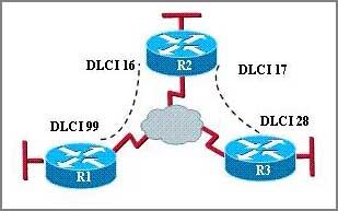
A: DLCI 17 describes the ISDN circuit between R2 and R3. B: DLCI 17 describes a PVC on R2. It cannot be used on R3 or R1. C: DLCI 17 is the Layer 2 address used by R2 to describe a PVC to R3. D: DLCI 17 describes the dial-up circuit from R2 and R3 to the service provider.
Answer: C
Explanation
DLCI stands for Data Link Connection Identifier. DLCI values are used on Frame Relay interfaces to distinguish between different virtual circuits. DLCIs have local significance because the identifier references the point between the local router and the local Frame Relay switch to which the DLCI is connected.
Question 4
Users have been complaining that their Frame Relay connection to the corporate site is very slow. The network administrator suspects that the link is overloaded. Based on the partial output of the Router#show frame relay pvc command shown in the graphic, which output value indicates to the local router that traffic sent to the corporate site is experiencing congestion?

A. DLCI=100 B. last time PVC status changed 00:25:40 C. in BECN packets 192 D. in FECN packets 147 E. in DF packets 0
Answer: C
Explanation
First we should grasp the concept of BECN & FECN through an example:
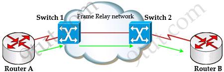
Suppose Router A wants to send data to Router B through a Frame Relay network. If the network is congested, Switch 1 (a DCE device) will set the FECN bit value of that frame to 1, indicating that frame experienced congestion in the path from source to destination. This frame is forwarded to Switch 2 and to Router B (with the FECN bit = 1).
Switch 1 knows that the network is congesting so it also sends frames back to Router A with BECN bit set to 1 to inform that path through the network is congested.
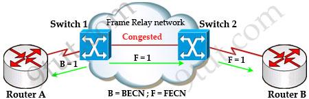
In general, BECN is used on frames traveling away from the congested area to warn source devices that congestion has occurred on that path while FECN is used to alert receiving devices if the frame experiences congestion.
BECN also informs the transmitting devices to slow down the traffic a bit until the network returns to normal state.
The question asks “which output value indicates to the local router that traffic sent to the corporate site is experiencing congestion” which means it asks about the returned parameter which indicates congestion -> BECN.
Question 5
What occurs on a Frame Relay network when the CIR is exceeded?
A. All TCP traffic is marked discard eligible. B. All UDP traffic is marked discard eligible and a BECN is sent. C. All TCP traffic is marked discard eligible and a BECN is sent. D. All traffic exceeding the CIR is marked discard eligible.
Answer: D
Explanation
Committed information rate (CIR): The minimum guaranteed data transfer rate agreed to by the Frame Relay switch. Frames that are sent in excess of the CIR are marked as discard eligible (DE) which means they can be dropped if the congestion occurs within the Frame Relay network.
Note: In the Frame Relay frame format, there is a bit called Discard eligible (DE) bit that is used to identify frames that are first to be dropped when the CIR is exceeded.
Question 6
What command is used to verify the DLCI destination address in a Frame Relay static configuration?
A show frame-relay pvc B. show frame-relay lmi C. show frame-relay map D. show frame relay end-to-end
Answer: C
Question 7
|
Router 1# show running-config interface serial0/0 bandwidth 64 ip address 172.16.100.2 255.255.0.0 encapsulation frame-relay frame-relay map ip 172.16.100.1 100 broadcast |

As a technician, you found the router1 is unable to reach the second router. Both routers are running IOS version 12.0. Based on this information, what is the most likely cause of the problem?
A. incorrect IP address B. incorrect bandwidth configuration C. incorrect map statement D. incorrect LMI configuration
Answer: C (In fact none is correct)
Explanation
First we have to say this is an unclear question and it is wrong. The “frame-relay map ip” statement is correct thus none of the four answers above is correct. But by the way we wish to explain about “global DLCI” in practical so you can understand it.
First we should remember that DLCI numbers are always only locally significant. “Global DLCI” is just a term to describe local DLCI numbers in a different manner and helps the documentation more easily.
First let’s see what happens if we use local DLCI as usual understanding:

Local DLCIs create a mess of notes!
With each connection, you have to note the DLCI number for that connection. For example, on router A we assign DLCI 100 for connection to router C; DLCI 200 to router D & DLCI 300 to router E. All of these numbers must be written on the links connecting to the corresponding routers. Now you can imagine we have about 100 routers, how many notes do we have to write?
That’s the reason why “global DLCI” comes into play. Notice that “global DLCI” term does not change the way DLCI works, it just changes the way we understand. The picture below demonstrates how this term is used.
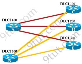
Global DLCIs help reduce the number of notes
In fact, both of the pictures above have the same configuration. And we should understand that “all connections to router C should be assigned DLCI 100 at the partner router of router C”. The same thing for router A “all connections to router A should be assigned DLCI 400 at routers C, D and E”.
Question 8
Refer to the exhibit. What is the meaning of the term dynamic as displayed in the output of the show frame-relay map command shown?
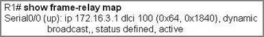
A. The Serial0/0 interface is passing traffic. B. The DLCI 100 was dynamically allocated by the router C. The Serial0/0 interface acquired the IP address of 172.16.3.1 from a DHCP server D. The DLCI 100 will be dynamically changed as required to adapt to changes in the Frame Relay cloud E. The mapping between DLCI 100 and the end station IP address 172.16.3.1 was learned through Inverse ARP
Answer: E
Explanation
The term dynamic indicates that the DLCI number and the remote router IP address 172.16.3.1 are learned via the Inverse ARP process.
Inverse ARP is a technique by which dynamic mappings are constructed in a network, allowing a device such as a router to locate the logical network address and associate it with a permanent virtual circuit (PVC).
Question 9
Refer to the exhibit. Which WAN protocol is being used?
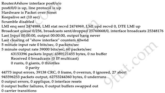
A. ATM B. HDLC C. Frame Relay D. PPP
Answer: C
Explanation
Local Management Interface (LMI) is a signaling standard protocol used between your router (DTE) and the first Frame Relay switch. From the output we learn this interface is sending and receiving LMI messages -> Frame Relay is being used.
Question 10
The command frame-relay map ip 10.121.16.8 102 broadcast was entered on the router. Which of the following statements is true concerning this command?
A. This command should be executed from the global configuration mode. B. The IP address 10.121.16.8 is the local router port used to forward data. C. 102 is the remote DLCI that will receive the information. D. This command is required for all Frame Relay configurations. E. The broadcast option allows packets, such as RIP updates, to be forwarded across the PVC.
Answer: E
Explanation
The command frame-relay map ip 10.121.16.8 102 broadcast means to mapping the distal IP 10.121.16.8 102 to the local DLCI 102. When the “broadcast” keyword is included, it turns Frame Relay network as a broadcast network, which can forward broadcasts.
CCNA Frame Relay 2
Question 1
What are two characteristics of Frame Relay point-to-point subinterfaces? (Choose two)
A. They create split-horizon issues. B. They require a unique subnet within a routing domain. C. They emulate leased lines. D. They are ideal for full-mesh topologies. E. They require the use of NBMA options when using OSPF.
Answer: B C
Question 2