


Ä
(3) Tip the torsion bar and drive motor assembly to the right side of the vehicle and slide the torsion bar out of the motor. Remove the drive motor from the vehicle (Fig. 10).
INSTALLATION
Reverse the preceding operation.
LAMPS 8L - 33
(7)Remove torsion bar anchor clip (Fig. 15).
(8)Slide torsion bar sleeve over the torsion bar (Fig. 16).
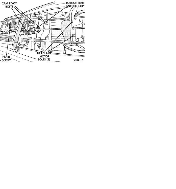
(9)Remove three clips retaining turn signal lamp shield to body (Fig. 17), and remove shield.
(10)Remove two screws retaining headlamp cover to headlamp cover bracket (Fig. 18).
(11)Remove outer headlamp.
(12)Remove outer pivot screw (Fig. 19).
(13)Remove E-clip and door crank screw (Fig. 20).
(14)Remove three bolts retaining cam pivot to body and remove cam pivot (Fig. 19).
(15)Remove Headlamp door assembly.
INSTALLATION
Reverse the preceding operation. Before installing torsion bar clips, the holes in the torsion bars, torsion bar sleeves and headlamp door cam pivots must be in alignment. Refer to Aligning Headlamp Doors.
Fig. 9 Torsion Bar and Motor Bolts
Fig. 10 Concealed Headlamp Drive Motor
HEADLAMP DOORÐAY BODY
REMOVAL
(1)Turn headlight switch ON.
(2)Open hood and locate Power Distribution Center forward of the left suspension tower (Fig. 11).
(3)Remove cover from the center and pull the Headlamp Close Relay (Fig. 12) to keep the headlamp doors from closing.
(4)Turn headlight switch OFF.
(5)Remove two grill mounting screws and remove grill assembly (Fig. 13).
(6)Spring tension must be relieved from the headlamp doors before removing headlamp motor torsion bar clips. Locate the thumb wheel on bottom of headlamp motor (Fig. 14). Rotate thumb wheel approximately six to seven turns clockwise to relieve all tension.
Fig. 11 Power Distribution Center
Fig. 12 Headlamp Close Relay
8L - 34 LAMPS |
|
Ä |
|
Fig. 13 Grille
Fig. 16 Torsion Bar Sleeves
Fig. 14 Headlamp MotorÐBottom View
Fig. 15 Torsion Bar Anchor Clips
HEADLAMP DRIVE MOTORÐAY BODY
REMOVAL
(1)Open headlamp doors. Refer to Headlamp Door paragraph for instructions.
(2)Remove two grille mounting screws and remove grille assembly (Fig. 13).
Fig. 17 Front Turn Signal Lamp Shield
Fig. 18 Headlamp Cover/Cover Pivot Bracket
(3)Spring tension must be relieved from headlamp doors before removing the headlamp motor torsion bar clips. Locate the thumb wheel on bottom of the headlamp motor (Fig. 14). Rotate thumb wheel approximately six to seven turns (clockwise) to relieve all tension.
(4)Remove both torsion bar anchor clips (Fig. 15).

Ä |
|
LAMPS 8L - 35 |
|
Fig. 19 Outer Pivot Screw
Fig. 20 Headlamp Pivot E-Clip and Crank Screw
(5)Slide torsion bar sleeves over the torsion bar (Fig. 16).
(6)Disconnect wire connector from motor.
(7)Remove motor mounting bolts (Fig. 19).
(8)Slide torsion bar through the headlamp motor (Fig. 21) and remove headlamp motor.
INSTALLATION
Reverse the preceding operation. Before installing torsion bar clips, the holes in the torsion bars, torsion bar sleeves and headlamp door cam pivots must be in alignment.
Fig. 21 Headlamp Motor
HEADLAMP DOOR ALIGNMENT
Door stop adjustment screws, and a movable cam pivot are used to adjust and align the headlamp doors.
Loosening the cam pivot bolts (Fig. 19) will allow an up/down or in/out adjustment of the headlamp doors.
Fig. 23 Cam Pivot Adjustment
The stop screws (Fig. 22) are also used to achieve proper tolerances.