


Ä |
|
IGNITION SYSTEMS 8D - 43 |
|
WARNING: THE ENGINE DIRECT IGNITION SYSTEM GENERATES APPROXIMATELY 40,000 VOLTS. PERSONAL INJURY COULD RESULT FROM CONTACT WITH THIS SYSTEM.
(2) With engine running, move test probe along entire length of all cables (approximately 0 to 1/8 inch gap). If punctures or cracks are present there will be a noticeable spark jump from the faulty area to the probe. Cracked, leaking or faulty cables should be replaced.
Use the following procedure when removing the high tension cable from the spark plug. First, remove the cable from the retaining bracket. Then grasp the terminal as close as possible to the spark plug. Rotate the cover (boot) slightly and pull straight back. Do not use pliers and do not pull the cable at an angle. Doing so will damage the insulation, cable terminal or the spark plug insulator. Wipe spark plug insulator clean before reinstalling cable and cover.
Resistance cables are identified by the words Electronic Suppression.
Use an ohmmeter to check cables for opens, loose terminals or high resistance.
(a)Remove cable from spark plug.
(b)Remove cable from the coil tower.
(c)Connect the ohmmeter between spark plug end terminal and the coil end terminal. Resistance should be within tolerance shown in the cable resistance chart. If resistance is not within tolerance, replace cable assembly. Test all spark plug cables in same manner.
CABLE RESISTANCE CHART
SPARK PLUG SERVICE
When replacing the spark plug cables, route the cables correctly and secure them in the appropriate retainers. Incorrectly routed cables can cause the radio to reproduce ignition noise. It can also cause cross ignition of the spark plugs or short circuit the cables to ground.
SPARK PLUG REMOVAL
Always remove cables by grasping at boot, rotating the boot 1/2 turn, and pulling straight back in a steady motion.
(1) Prior to removing the spark plug spray compressed air around the spark plug hole and the area around the spark plug.
(2)Remove the spark plug using a quality socket with a rubber or foam insert.
(3)Inspect the spark plug condition. Refer to Spark Plug Condition in this section.
SPARK PLUG GAP ADJUSTMENT
Check the spark plug gap with a gap gauge. If the gap is not correct, adjust it by bending the ground electrode (Fig. 6).
Fig. 6 Setting Spark Plug GapÐTypical
SPARK PLUG INSTALLATION
(1)To avoid cross threading, start the spark plug into the cylinder head by hand.
(2)Tighten spark plugs to 28 NIm (20 ft. lbs.) torque.
(3)Install spark plug cables over spark plugs.
IDLE RPM TEST
WARNING: BE SURE TO APPLY PARKING BRAKE AND/OR BLOCK WHEELS BEFORE PERFORMING ANY ENGINE RUNNING TESTS.
Engine idle set rpm should be tested and recorded as it is when the vehicle is first brought into shop for testing. This will assist in diagnosing complaints of engine stalling, creeping and hard shifting on vehicles equipped with automatic transmissions.
Proceed to the Throttle Body Minimum Airflow procedures.

8D - 44 IGNITION SYSTEMS
THROTTLE BODY MINIMUM AIR FLOW CHECK PROCEDUREÐTURBO III
(1)Warm engine in neutral until the cooling fan has cycled on and off at least once.
(2)Shut off engine.
(3)Hook-up Tachometer.
(4)Disconnect the PCV valve hose from the nipple on the intake manifold.
(5)Attach air metering fitting, special tool #6457 (0.125 inch orifice), to the intake manifold PCV nipple (Fig. 7).
Fig. 7 Air Metering Fitting #6457
(6)Disconnect 3/16 inch manifold vacuum purge line from the top of the throttle body. Cap the 3/16 inch throttle body nipple.
(7)Connect Diagnostic Readout Box II (DRB II).
(8)Restart engine. Allow engine to idle for at least one minute.
(9)Using the DRB II, access Min. Airflow Idle Spd. The following will then occur:
²AIS motor will fully close.
²Idle spark advance will become fixed.
²Engine RPM will be displayed on Diagnostic Readout Box II (DRB II).
(10)Check idle RPM with tachometer, if idle RPM is within the below specification then the throttle body minimum airflow is set correctly.
IDLE SPECIFICATIONS
If the idle RPM is not within specification, replace the throttle body.
(11) Shut off engine.
Ä
(12)Remove air metering fitting 6457 from the intake manifold PCV nipple. Connect the PCV hose to the nipple.
(13)Remove DRB II.
(14)Disconnect tachometer.
(15)Reconnect purge line to throttle body.
THROTTLE BODY MINIMUM AIR FLOW CHECK PROCEDUREÐ3.3L AND 3.8L ENGINES
(1)Warm engine in Park or Neutral until the cooling fan has cycled on and off at least once.
(2)Ensure that all accessories are off.
(3)Shut off engine.
(4)Disconnect the PCV valve hose from the intake manifold nipple.
(5)Attach Air Metering Fitting #6457 (0.125 in. orifice) to the intake manifold PCV nipple (Fig. 7).
(6)Disconnect the 3/16 inch idle purge line from the throttle body nipple. Cap the 3/16 inch nipple.
(7)Connect Diagnostic Readout Box II (DRB II).
(8)Restart the engine. Allow engine to idle for at least one minute.
(9)Using the DRBII, access Min. Airflow Idle Spd.
(10)The following will then occur:
²AIS motor will fully close.
²Idle spark advance will become fixed.
²Engine RPM will be displayed on DRB II.
(11)If idle RPM is within the range shown in the Idle Specification chart, throttle body minimum airflow is set correctly.
IDLE SPECIFICATIONS
(12) If idle RPM is not within specifications, shut off the engine and clean the throttle body as follows:
(a) Remove the throttle body from engine.
WARNING: CLEAN THROTTLE BODY IN A WELL VENTILATED AREA. WEAR RUBBER OF BUTYL GLOVES, DO NOT LET MOPAR PARTS CLEANER COME IN CONTACT WITH EYES OR SKIN. AVOID INGESTING THE CLEANER. WASH THOROUGHLY AFTER USING CLEANER.
(b) While holding the throttle open, spray the entire throttle body bore and the manifold side of the

Ä |
|
IGNITION SYSTEMS 8D - 45 |
|
throttle plate with Mopar Parts Cleaner. Only use
Mopar Parts Cleaner to clean the throttle body.
(c)Using a soft scuff pad, clean the top and bottom of throttle body bore and the edges and manifold side of the throttle blade. The edges of the throttle blade and portions of the throttle bore that are closest to the throttle blade when is closed, must be free of deposits.
(d)Use compressed air to dry the throttle body.
(e)Inspect throttle body for foreign material.
(f)Install throttle body on manifold.
(g)Repeat steps 1 through 14. If the minimum air flow is still not within specifications, the problem is not caused by the throttle body.
(13)Shut off engine.
(14)Remove Air Metering Fitting #6457 from the intake manifold PCV nipple. Reinstall the PCV valve hose.
(15)Uncap the throttle body idle purge nipple and connect the idle purge line.
(16)Remove DRB II.
IGNITION TIMING PROCEDURE
Ignition timing cannot be changed or set on Turbo III, 3.3L or 3.8L engines. For diagnostic information, refer to the DRB II tester and the appropriate Powertrain Diagnostics Procedures manual.
CRANKSHAFT SENSORÐTURBO III ENGINE
REMOVAL
(1)Remove throttle body.
(2)Remove inter-cooler to turbo-charger air hose.
(3)Disconnect crank timing sensor pick-up lead at wiring harness connector (Fig. 8).
Fig. 8 Crankshaft Sensor ServiceÐTurbo III Engine
(4)Remove crank timing sensor retaining bolt.
(5)Pull crank timing sensor straight up out of the transaxle housing.
INSTALLATION
(1)Install sensor in transaxle. Push sensor down until contact is made with the transaxle housing.
Hold the sensor in this position. Install and tighten retaining bolt to 16 NIm (145 in. lbs.) torque.
(2)Connect electrical connector to sensor.
CRANKSHAFT SENSORÐ3.3L AND 3.8L ENGINES
REMOVAL
(1) Disconnect crankshaft timing sensor electrical connector from the wiring harness connector (Fig. 9).
Fig. 9 Crankshaft Timing SensorÐ3.3L and 3.8L
Engines
(2)Remove crankshaft timing sensor retaining bolt.
(3)Pull crankshaft timing sensor straight up out of the transaxle housing.
INSTALLATION
If installing the original sensor, clean off the old spacer on the sensor face. A NEW SPACER must be attached to the sensor face before installation. If the sensor is being replaced, confirm that the paper spacer is attached to the face of the new sensor (Fig. 10).
Fig. 10 Crankshaft Sensor and Spacer
(1) Install sensor in transaxle and push sensor down until contact is made with the drive plate.

8D - 46 IGNITION SYSTEMS
While holding the sensor in this position, and install and tighten the retaining bolt to 12 NIm (105 in. lbs.) torque.
(2) Connect crankshaft timing sensor electrical connector to the wiring harness connector.
CAMSHAFT SENSOR SERVICEÐTURBO III ENGINE
REMOVAL
(1) Disconnect cam reference sensor lead at wiring harness connector (Fig. 11).
Fig. 11 Camshaft Sensor LocationÐTurbo III En-
gines
(2) Remove camshaft timing sensor retaining bolt and remove sensor.
INSTALLATION
If installing the original sensor, clean off the old spacer on the sensor face. A NEW SPACER must be attached to the face before installation.
If the sensor is being replaced, confirm that the paper spacer is attached to the face (Fig. 12).
Fig. 12 Camshaft SensorÐTurbo III Engine
Ä
(1)Install sensor in the cylinder head and push sensor down until contact is made with the camshaft
gear. While holding the sensor in this position, install and tighten the retaining bolt 16 NIm (145 in. lbs.) torque.
(2)Connect electrical connector to the camshaft sensor.
CAMSHAFT SENSORÐ3.3L AND 3.8L ENGINES
REMOVAL
(1) Disconnect camshaft reference sensor electrical connector from the wiring harness connector (Fig. 13).
Fig. 13 Camshaft Sensor LocationÐ3.3L and 3.8L
Engine
(2)Loosen camshaft timing sensor retaining bolt enough to allow slot in sensor to slide past the bolt.
(3)Pull sensor up out of the chain case cover. Do not pull on the sensor lead. There is an O-ring on the sensor case. The O-ring may make removal difficult. A light tap to top of sensor prior to removal may reduce force needed for removal.
INSTALLATION
If installing the original sensor, clean off the old spacer on the sensor face. A NEW SPACER must be attached to the face before installation.
Inspect O-ring for damage, replace if necessary. If the sensor is being replaced, confirm that the paper spacer is attached to the face and O-ring is positioned in groove of the new sensor (Fig. 14).
(1)Apply a couple drops of clean engine oil to the O-ring prior to installation. Install sensor in the chain case cover and push sensor down until contact is made with the cam timing gear. While holding the
sensor in this position, install and tighten the retaining bolt 12 NIm (105 in. lbs.) torque.
(2)Connect camshaft reference sensor electrical connector to harness connector. Position connector away from the accessory belt.
Ä |
|
IGNITION SYSTEMS 8D - 47 |
|
Fig. 14 Camshaft SensorÐ3.3L and 3.8L Engines
IGNITION COIL SERVICEÐTURBO III ENGINE
(1) Remove spark plug cables from coil (Fig. 15).
Fig. 15 Ignition Coil ServiceÐTurbo III
(2)Remove electrical connector from coil pack.
(3)Remove ignition coil fasteners.
(4)Reverse the above procedure for installation. Tighten fasteners to 12 NIm (105 in. lbs.) torque.
IGNITION COILÐ3.3L AND 3.8L ENGINE
(1)Remove spark plug cables from coil (Fig. 16).
(2)Remove ignition coil electrical connector.
(3)Remove ignition coil mounting screws.
(4)Remove ignition coil.
Reverse the above procedure for installation. Tighten mounting screws to 12 NIm (105 in. lbs.) torque.
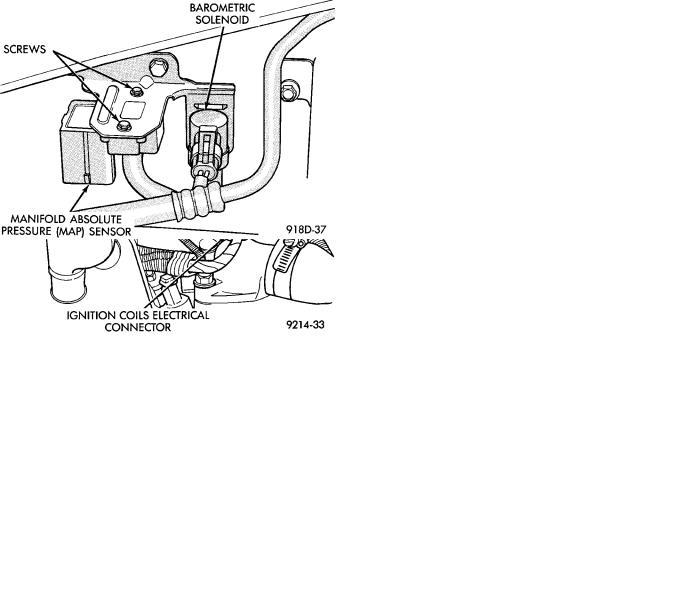
MANIFOLD ABSOLUTE PRESSURE (MAP) SENSORÐTURBO III ENGINE
The map sensor mounts to the right front fender (Fig. 17).
(1)Remove vacuum hose from MAP sensor.
(2)Remove MAP sensor mounting screws.
(3)Remove electrical connector from sensor.
(4)Reverse procedure for installation.
Fig. 16 Ignition Coil Removal and Installation
Fig. 17 MAP SensorÐTurbo III Engine
MANIFOLD ABSOLUTE PRESSURE (MAP) SENSORÐ3.3L AND 3.8L ENGINES
The alignment of the MAP sensor is critical to the sensors performance. The top of the sensor is marked This Side Up (Fig. 18).
(1)Disconnect electrical connector from MAP sen-
sor.
(2)Remove sensor by unscrewing from the intake manifold (Fig. 18).
(3)Reverse the above procedure for installation.