

8D - 12 IGNITION SYSTEMS |
|
Ä |
|
Inspect the coil for arcing. Test the coil according to coil tester manufacturer's instructions. Test coil primary and secondary resistance. Replace any coil that does not meet specifications. Refer to the Coil Resistance chart.
If the ignition coil is replaced due to a burned tower, carbon tracking, arcing at the tower, or damage to the terminal or boot on the coil end of the secondary cable, the cable must be replaced. Arcing at the tower will carbonize the nipple which, if it is connected to a new coil, will cause the coil to fail.
If a secondary cable shows any signs of damage, the cable should be replaced with a new cable and new terminal. Carbon tracking on the old cable can cause arcing and the failure of a new coil.
TESTING FOR SPARK AT COIL
WARNING: APPLY PARKING BRAKE AND/OR BLOCK THE WHEELS BEFORE PERFORMING ANY TEST WITH THE ENGINE RUNNING.
CAUTION: Spark plug cables may be damaged if this test is performed with more than 1/4 inch clearance between the cable and engine ground.
Remove the coil secondary cable from the distributor cap. Hold the end of cable about 6 mm (1/4-inch) away from a good engine ground (Fig. 1). Crank the engine and inspect for spark at the coil secondary cable.
Fig. 1 Checking for Spark
There must be a constant spark at the coil secondary cable. If the spark is constant, have a helper continue to crank engine and, while slowly moving coil secondary cable away from ground, look for arcing at the coil tower. If arcing occurs at the tower, replace the coil. If spark is not constant or there is no spark, proceed to the failure to start test.
If a constant spark is present and no arcing occurs at the coil tower, the ignition system is producing the
necessary high secondary voltage. However, make sure that the spark plugs are firing. Inspect the distributor rotor, cap, spark plug cables, and spark plugs. If they are in proper working order, the ignition system is not the reason why the engine will not start. Inspect the fuel system and engine for proper operation.
FAILURE TO START TESTÐ2.5L TBI AND 3.0L ENGINES
Before proceeding with this test make sure Testing For Spark At Coil has been performed. Failure to do this may lead to unnecessary diagnostic time and wrong test results.
WARNING: BE SURE TO APPLY PARKING BRAKE AND/OR BLOCK WHEELS BEFORE PERFORMING ANY TEST WITH THE ENGINE RUNNING.
(1)Battery voltage must be at least 12.4 volts to perform test.
(2)Crank the engine for 5 seconds while monitoring the voltage at the coil positive (+) terminal (Fig. 2 or Fig. 3). If the voltage remains near zero during the entire period of cranking, refer to Group 14 for OnBoard Diagnostic checks. Also, refer to the DRB II tester and the appropriate Powertrain Diagnostic Procedures manual. These checks will help diagnose problems with the engine controller and auto shutdown relay.
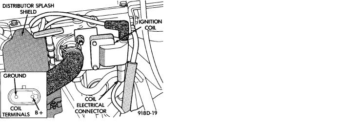
Fig. 2 Coil TerminalsÐ2.2L TBI, 2.5L TBI and
Turbo I Engines
(3)If voltage is at near-battery voltage and drops to zero after 1-2 seconds of cranking, refer to On-Board Diagnostic in Group 14. Also, refer to the DRB II tester and the appropriate Powertrain Diagnostic Procedures manual. These tests will help check the distributor reference pickup circuit to the engine controller.
(4)If voltage remains at near battery voltage during the entire 5 seconds, with the key off, remove

Ä |
|
IGNITION SYSTEMS 8D - 13 |
|
Fig. 3 Coil TerminalsÐ3.0L Engine
the engine controller 60-way connector. Check the 60-way connector for any terminals that are pushed out or loose.
(5)Remove the connector to coil (+) and connect a jumper wire between battery (+) and coil (+).
(6)Using the special jumper (Fig. 4), momentarily ground terminal #19 of the 60-way connector (Fig. 5). A spark should be generated when the ground is removed.
Fig. 4 Special Jumper to Ground Coil Negative
Fig. 5 60-Way Electrical Connector, Engine
Controller
(7)If spark is generated, replace the engine controller.
(8)If no spark is seen, use the special jumper to ground the coil (-) terminal directly.
(9)If spark is produced, inspect wiring harness for an open condition.
(10) If no spark is produced, replace the ignition coil.
POOR PERFORMANCE TEST
To prevent unnecessary diagnostic time and possible incorrect results, the Testing For Spark At Coil procedure should be performed before this test.
WARNING: APPLY PARKING BRAKE AND/OR BLOCK THE WHEELS BEFORE PERFORMING ANY ENGINE RUNNING TESTS.
Check and adjust basic timing (refer to the specification section of this group and see service procedures).
COOLANT TEMPERATURE SENSOR TEST
(1)With key off, disconnect wire connector from coolant temperature sensor (Fig. 6).
(2)Connect one lead of ohmmeter to one terminal of coolant temperature sensor.
(3)Connect the other lead of ohmmeter to remaining terminal of coolant temperature sensor. The ohmmeter should read as follows;
²Engine/Sensor at normal operating temperature around 200°F should read approximately 700 to 1,000 ohms.
²Engine/Sensor at room temperature around 70°F, ohmmeter should read approximately 7,000 to 13,000 ohms.
Refer to On Board Diagnostics in the General Diagnosis section of Group 14. Also, refer to the DRB II tester and the appropriate Powertrain Diagnostic Procedures manual for additional test procedures.
Fig. 6 Coolant Temperature Sensor Test
MANIFOLD ABSOLUTE PRESSURE (MAP) SENSOR TEST
Refer to the DRB II tester and appropriate Powertrain Diagnostic Procedures manual for further test procedures.
DETONATION (KNOCK) SENSOR
Refer to the DRB II tester and appropriate Powertrain Diagnostic Procedures manual for test procedures.