

Sensory Organ Replacement and Repair - Gerald E. Miller
.pdf36 SENSORY ORGAN REPLACEMENT AND REPAIR
or enforcement reports for each device. There have been no approved devices by the FDA since 2001.
In 2004, Advanced Bionics issued a voluntary recall of its Clarion cochlear implants because there were noted moisture problems prior to implantation for some of their devices. This report is reported at http://www.fda.gov/bbs/topics/news/2004/NEW01119.html. The FDA also issued a report on the risk of bacterial meningitis in small children receiving cochlear implants. This report is at http://www.fda.gov/cdrh/safety/cochlear.html.
As with any technology that has received few approved applications over 20 years including none over the last 5 years, there are still significant questions to answer. Is the use of the device hampered by the nonsupport of the deaf community or due to the checkered success rate for profoundly deaf patients (from birth) who have no basis to understand spoken language as processed by a cochlear implant? The FDA Web site that analyzes risks and benefits ishttp://www.fda.gov/cdrh/cochlear/RiskBenefit.html.
There have been numerous published reports regarding clinical and empirical research on cochlear implants. These can generally be categorized as reports regarding the use of cochlear implants in children, the use of cochlear implants in the elderly, a comparison of cochlear implants versus hearing aids, and studies regarding design issues, such as electrode configuration and signal processing techniques. Recent studies regarding the use of cochlear implants in small children include those by Beadle et al. (2005), Berg et al. (2005), Biernath et al. (2006), Flipsen and Colvard (2005), Gordon et al. (2005), Henkin et al. (2005), Higgins et al. (2005), Hyde and Power (2005), and Tomblin et al. (2005), among others.
Studies regarding the use of cochlear implants in the elderly include those by Haensel et al. (2005) and Hay-McCutcheon et al. (2005), among others, while the studies regarding design considerations include Fabry (2005), Fu et al. (2005), Hong and Rubinstein (2006), Laneau et al. (2005), Munson and Nelson (2005), Stickney et al. (2005a), Stickney et al. (2005b), Vermeire et al. (2006), and Xu et al. (2005), among others.
Despite the relatively small numbers of FDA approved devices, the number of worldwide implants is growing, and the number of clinical studies and published reports number in the thousands.
4 INTRAOCULAR LENS
4.1Anatomy of the Eye
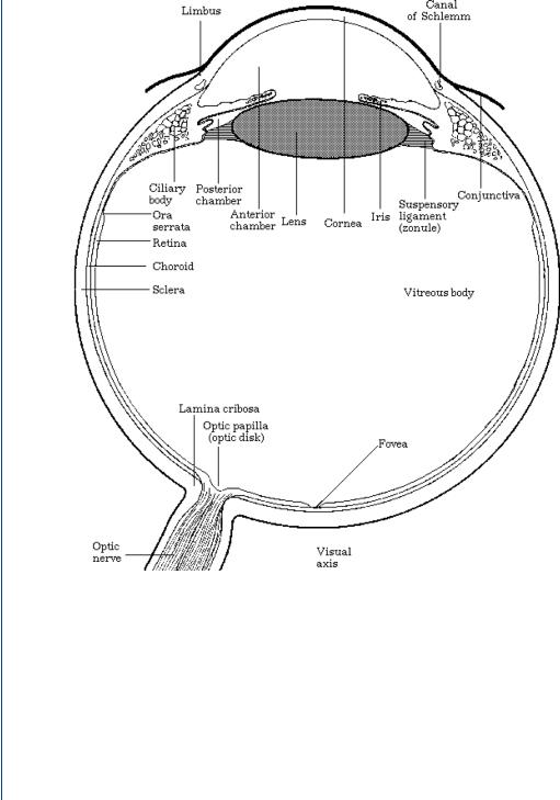
An IOL is used to replace a damaged lens in the eye, most normally due to a cataract, which results in cloudy vision. The human eye, shown in Figure 40, consists of the multilayer outer covering (the cornea), the iris and associated pupil opening, the lens inside a lens sac, and the retina. There are fluid layers between the cornea and the lens and again between the lens and the

INTRAOCULAR LENS 37
FIGURE 40: Anatomy of the human eye.
retina. The retina ends with the optic nerve. The cornea provides 75% of the overall focusing power of the eye with the lens proving the other 25%.
However, it is the ability of the natural lens to accommodate, to change focal length, and the fine tuning of accurate sight that is key to visual field acuity. The human lens is a gelatinous substance, which is flexible. This is important as the sac in which it resides is connected on either end by ciliary muscles. These muscles can rapidly move in and out. As your visual attention moves closer or farther away, the ciliary muscles (sometimes called the ciliary body) attached to your lens sac move in and out, which changes the shape of the lens to make it more or less concave and provide variable focus. This process is called accommodation. When one looks directly at one’s feet and then suddenly attempts to focus 50 yards away, the focus remains true and one’s visual field remains perfectly clear. This could not happen without the lens being able to change its shape as the lens sac is pulled by the attached muscles. The continuing change in the shape of the lens allows the focal point of vision to fall on a section of the retina known as the fovea. A more detailed view of the human eye showing the fovea on the retina is shown in Figure 41.
4.2Cataracts and Their Determination
A cataract is a clouding of the human lens with the resulting vision becoming opaque in that eye. Often, if only one eye is affected, it may be possible that an individual does not realize that a
38 SENSORY ORGAN REPLACEMENT AND REPAIR
FIGURE 41: Anatomy of the human eye showing the fovea portion of the retina.
cataract is evident. Over 40 million people in the United States suffer from cataracts. A cataract can result from many sources, including age, diabetes, glaucoma, blunt injury, excessive infrared light exposure, excessive steroids, and genetic effects. The natural lens, which is crystalline in nature, becomes opaque and less flexible with an advanced cataract. This results in the lens becoming less able to accommodate by changing shape. However, it is the opaque vision effect of a cataract that is often more telling in both the diagnosis and the patient complaint. A routine eye examination with a slit lamp would indicate a cataract, since the eye would show whiteness in the lens indicating cloudy vision. A typical slit lamp examination is shown in Figure 42.

INTRAOCULAR LENS 39
FIGURE 42: Typical slit lamp examination to examine the interior of the eye.
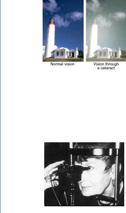
Figure 43 shows both a normal eye (front view) and an eye with a cloudy lens. It is obviously easy to see this in a routine eye examination. The resulting visual field is different for a normal lens and a cloudy lens, as is shown in Figure 44. The opaque nature of the visual field is easier to notice by the patient in sunlight and is less easy to notice in artificial (indoor) light.
Once a cataract has been determined to exist, it is necessary to evaluate the location of the lens, its distance from the cornea and from the retina, the thickness of the lens, and the size of the sac. This will eventually allow the clinician to determine the correct power and size of an artificial lens, the intraocular lens. This geometric and anatomical information of the eye requires detailed measurements within the fluid-filled eye with a resolution that is on the order of 0.1 mm. The use of ultrasound at a high frequency is perfect for this determination for several reasons: 1) ultrasound transmits well within a liquid; 2) at a 10–15-MHz emission frequency, the resolution is on the order of the required 0.1 mm; and 3) the attenuation factor for ultrasound
FIGURE 43: Views of human lens: normal lens on the left and cloudy lens on the right.
40 SENSORY ORGAN REPLACEMENT AND REPAIR
FIGURE 44: Visual field for a normal lens on the left and a cloudy lens on the right.
is lessened due to the small depth of the eye. A typical A-scan ultrasound examination of the eye is shown in Figure 45.
The ultrasound probe is a small 3-mm rod attached to a spring-loaded micrometer device, sometimes called a Goldman tonometer holder. The clinician slowly rotates a knob and the probe slowly nears the patient’s eye. When the probe contacts the cornea and meets resistance, it automatically springs backward away from the patient. This actually gives the sufficient time to make the appropriate measurement, since the 10-MHz emission frequency is actually pulsed 1000 times per second. As a result, each 1-ms pulse width contains 10 000 emitted pulses at the 10-MHz frequency (each emitted wave being 0.1 μs). Thus, in as little as 1 ms of contact
FIGURE 45: A scanner for the eye.
INTRAOCULAR LENS 41
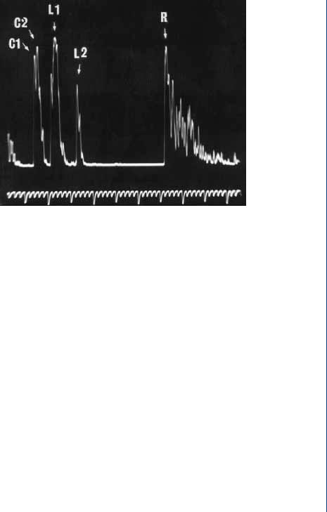
FIGURE 46: A-scan ultrasound pulse-echo pattern in the eye.
with the cornea, the A-scan probe would have emitted 10 000 pulses with the returning echoes processed for turnaround time. This turnaround time duration is equivalent to the distance from the probe (and thus the cornea outer edge), since a constant speed of sound is assumed. A typical A-scan ultrasound pulse-echo pattern is shown in Figure 46.
The C1 and C2 echoes in Figure 46 refer to the anterior and posterior surfaces of the cornea, while the L1 and L2 echoes refer to the anterior and posterior surfaces of the lens, and the R echo refers to the anterior surface of the retina. The various distances from the cornea to the lens and from the lens to the retina dictate the power of whatever replacement lens is required. Any variation in measurements of these distances can affect the final power of the implanted lens, and this depends on the axial length (depth) of the eye. In an average 23.5-mm eye, a 0.1-mm difference in axial length measurement (of the eye) affects the final postoperative refraction by 0.25 D (D = diopter, the standard optical power for lenses). In a long 26.0-mm eye, a 0.1-mm difference in the AL measurement affects the final postoperative refraction by only 0.20 D. In the short 2l.0-mm eye, a 0.1-mm difference in the axial length measurement affects the final postoperative refraction by 0.31 D.
4.3The IOL and Implantation Surgery
An IOL is a replacement device for a cloudy natural lens. Because of the small size of the natural lens and the lens sac, along with a need to have very small incisions for removal of the old lens and insertion of the replacement lens, there is a size restriction on the artificial lens and any

42 SENSORY ORGAN REPLACEMENT AND REPAIR
device to hold this lens. Furthermore, as this is a device that will be in close contact with liquids and tissues inside the body, this device must be biocompatible and nonreactive. Obviously, this device must have the correct optical power as determined by the A-scan ultrasonic examination of the eye. As will be described below, the standard IOL is pliable and can be folded in half during insertion, so as to limit the size of the incision.
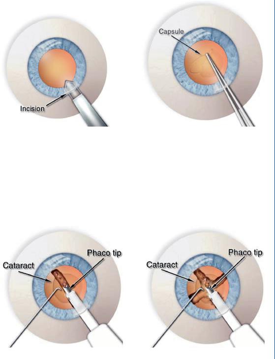
However, first things first. The cloudy natural lens must somehow be removed in order to have space for the replacement IOL. As the natural lens is a crystalline, gelatinous material, we can employ various technologies to remove this lens from the eye. The most commonly employed technique is to use high-frequency, therapeutic level ultrasound, often called phacoemulsification. Unlike the A-scan ultrasound used to measure eye distances, the ultrasound used to emulsify the natural lens is not a pulse-echo device, but rather a continuous wave device. The pulse-echo device is actually “on” for 1% of the time with the other 99% in the echo mode to detect the time course of returning echoes. In the continuous wave mode, particularly with higher amplitudes than the pulse-echo mode, the tissues or fluids can vibrate and even heat up. Therapeutic ultrasound is sometimes employed to ease aching muscles by heating the tissue and increasing blood flow to the region. In phacoemulsification, the gelatinous lens is liquefied (emulsified) and then aspirated out, leaving an empty sac behind.
The cataract surgical procedure consists of the following steps:
1.An outer incision to the edge of the cornea
2.An inner incision in the lens sac
3.Phacoemulsification of the natural lens
4.Aspiration of the liquefied natural lens
5.Insertion of the folded IOL
6.Suture the lens sac with dissolvable sutures
7.Suture the outer incision with nondissolvable sutures
Both incisions are approximately 3 mm long. Figure 47 depicts the miniature scalpel used to create the microincisions. The surgeon creates an opening in the lens capsule, which is a microthin membrane surrounding the cataract. This procedure, called capsulorhexus, requires extraordinary precision since the capsule is only about four-thousandths of a millimeter thick.
A typical phacoemulsification probe is shown in Figure 48 with the ultrasound waves seen emanating within the lens.
Figure 49 shows the aspiration portion of the process once the lens has been fully emulsified (liquefied). The aspiration probe is moved around the sac to completely aspirate all loose materials within the sac, as is shown in Figure 49.
INTRAOCULAR LENS 43
FIGURE 47: Incisions in cataract surgery: left—on the side of the cornea with a miniature scalpel and right—on the side of the lens sac.
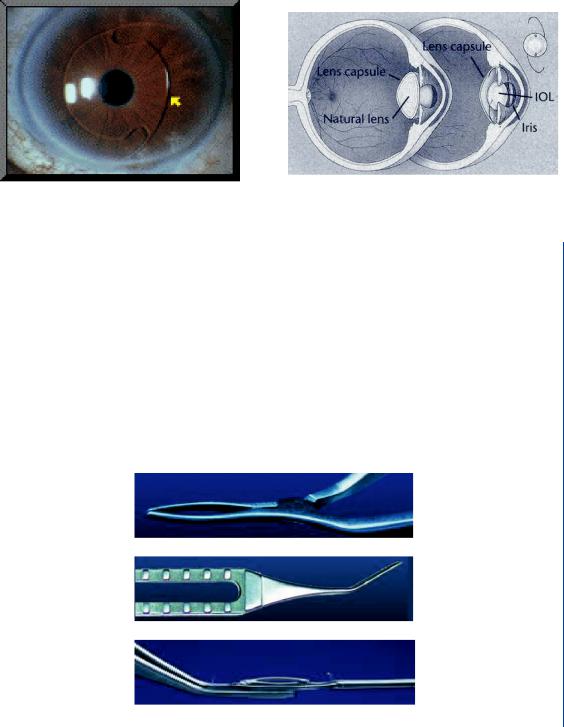
Once the original cloudy lens has been removed, it is then possible to insert the IOL. A typical IOL is shown in Figure 50 and consists of a biconvex, clear lens with “wings” to hold the lens in place within the lens sac/capsule.
The springlike wings pop out when the IOL is unfolded during insertion. A diagram with the IOL in place within the eye as compared to the natural lens is shown in Figure 51.
FIGURE 48: Phacoemulsification showing the sound waves with breakup of lens to left.

44 SENSORY ORGAN REPLACEMENT AND REPAIR
FIGURE 49: Irrigation and aspiration of the emulsified lens. Aspiration probe is moved around the lens sac to aspirate all particles and lens pieces.
A typical IOL is a clear lens made of an acrylic polymer with 25–30% water content, so that it will not absorb water when inserted into the fluid-filled environment of the human eye (aqueous and vitreous regions as noted in Figures 40 and 41). An IOL has various optical powers based upon patient needs. It is typically 6–8 mm in diameter and is available in a power range between 10 and 30 D in 0.5-D increments. Other IOL’s are made of silicone, poly(methyl methacrolate) (PMMA), or a clear polymer known as perspex. Many IOL designs have ultraviolet light blockers incorporated into the lens material.
As was stated earlier, it is necessary to fold the IOL during insertion, as the 6–8-mm diameter is larger than the incision width of 3–4 mm. Thus, specialized tools are used to fold and
FIGURE 50: Typical IOL with wings.
INTRAOCULAR LENS 45
FIGURE 51: IOL in place within the eye and lens sac/capsule.
hold the IOL as well as release it once it is placed within the lens sac/capsule. A forceps design is offered by various IOL manufacturers which folds and holds the lens while it is inserted into the capsule. Typical forceps designs are shown in Figure 52.
Once the IOL is placed within the lens capsule, the IOL is then released and it pops open within the capsule with the spring-loaded wings extending outward. Other forms of IOL holders include injection-type devices with push button or screw-turned hold and release mechanisms, as is shown in Figure 53.
Following implantation, the slit at the edge of the lens sac/capsule is often sutured with dissolvable sutures. The outer slit at the edge of the cornea is closed with nondissolvable sutures. The patient is given strong wraparound sunglasses, as there will be a strong light sensitivity for
FIGURE 52: IOL forceps designs that hold the folded IOL for insertion into the lens sac.