

Cohen M.F., Wallace J.R. - Radiosity and realistic image synthesis (1995)(en)
.pdfCHAPTER 10. EXTENSIONS
10.3 PARTICIPATING MEDIA
150, 264]. Volume rendering for hierarchical volumes is explored in [145]. During rendering, the equation 10.29 is evaluated for each pixel. First, the contribution of the radiosity of the visible surface is computed, taking into account attenuation by computing τ as above. Then the contribution to the total radiance of every volume element through which the path travels is computed, also taking into account the attenuation based on the distance from the eye to the volume element. The final radiance for the pixel is the sum of all these contributions. Since J is computed independently of the view, rendering another view requires only recomputing these path integrals.
As in conventional radiosity, constant volume elements are not adequate for rendering. Trilinear interpolation can be used to smooth the volume radiosities during rendering. Results of this method are shown in color plates 1f and 48.
The zonal method has been extended by Rushmeier [198] to this media exhibiting weak anisotropic scatter, where volume-to-volume interactions are assumed insignificant. It has been further extended by Bhate and Tokuta [28] to the case of more general anisotropic scatter, using spherical harmonics to approximate the directionally dependent phase function.
Radiosity and Realistic Image Synthesis |
330 |
Edited by Michael F. Cohen and John R. Wallace |
|
CHAPTER 11. APPLICATIONS AND RESEARCH
Chapter 11
Applications and Research
This chapter will explore the use of radiosity in design, engineering and scientific applications; the experimental validation of the radiosity method; and opportunities for research into improved models, numerical methods, and algorithms.
Applications and research are not as independent as they might seem at first glance. The incorporation of radiosity into an application precipitates a whole new set of requirements that can push research in unexpected and fruitful directions. The difference between algorithms suitable for specialists and algorithms for mainstream use is not trivial. Since image synthesis is often just a tool hidden inside a larger application, it is expected to perform robustly and predictably with little technical input from the user. This places great demands on the underlying algorithms. The development of automatic, accurate, and robust algorithms will provide research problems for a long time to come.
11.1 Applications
In general, radiosity is most useful in applications where ideal diffuse interreflection is important and the geometry is static. The view-independent approach is particularly valuable when the exploration of a three-dimensional model is required, rather than the production of a single static image.
When incorporating any global illumination algorithm into an application, it is important to insulate the user from the technical details of the procedure. Specifying a mesh resolution or adaptive subdivision criterion forces the user to learn entirely new concepts unrelated to his or her work. To the extent that the user is given control over the solution, results must be predictable. Radiosity solutions for complex environments are too expensive to allow trial and error as a reasonable approach.
These requirements have important consequences for the development of radiosity algorithms. Meshing algorithms must be extremely robust. Where parameters are necessary, they must map clearly to quality and cost. The timequality tradeoff should be predictable, and quality should degrade gracefully
Radiosity and Realistic Image Synthesis |
331 |
Edited by Michael F. Cohen and John R. Wallace |
|
CHAPTER 11. APPLICATIONS AND RESEARCH
11.1 APPLICATIONS
with decreasing cost. For example, a lower-cost solution might provide less shadow detail, but should not contain disturbing artifacts.
In the next sections, several radiosity applications will be discussed. This will highlight some of the strengths of the radiosity approach, as well as some of the areas that need attention.
11.1.1 Architectural Design
Architectural design is in many ways an ideal application for image synthesis and the radiosity method in particular. Architects must communicate a design to clients, who may have difficulty visualizing the final building from abstract plans and drawings. As a result, architects currently depend on hand-drawn or painted perspectives, or on expensive physical models to provide a concrete representation. These media allow the designer to communicate a valuable emotional or aesthetic impression, but they also have limitations. For example, they can convey only a limited sensation of interior space, since they do not allow the client to look around or to explore the design from different viewpoints. Because they are time consuming to produce, they do not encourage the exploration of alternative materials, finishes, or lighting. For these reasons, the prospect of producing realistic three-dimensional renderings quickly and automatically has made image synthesis attractive.
Radiosity is particularly well suited to architectural design. Many interior surfaces (e.g., upholstery, textiles, matte paints) are reasonably well approximated by ideal diffuse reflection, and diffuse interreflection makes an important contribution to the illumination of interiors. Architectural models are usually static. The radiosity solution, when rendered on a graphics workstation, allows interactive walkthroughs of the shaded model, giving the designer and the client the opportunity to explore the interior space interactively.
Typical features of a radiosity application for architecture would include
•Translation from modeler data formats.
•Access to material libraries.
•Access to lighting libraries.
•Positioning of lights.
•Assignment of material properties.
•Positioning of texture maps.
Radiosity and Realistic Image Synthesis |
332 |
Edited by Michael F. Cohen and John R. Wallace |
|
CHAPTER 11. APPLICATIONS AND RESEARCH
11.1 APPLICATIONS
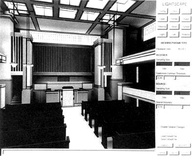
Figure 11.1: A view of the Lightscape architectural design application. The model shown is Frank Lloyd Wright’s Unity Temple designed in 1904. Image courtesy of Stuart Feldman Lightscape Graphics Software.
•Control over the process of the solution. Progressive refinement is useful because it allows the user to evaluate the partial solution without having to wait for convergence.
•Camera control for interactive walkthroughs.
Radiosity simulations also have some limitations for architectural visualization. Although ideal diffuse reflection is a reasonable approximation for many common surfaces, many other common surface materials and finishes cannot be represented correctly (e.g., metals, polishes, glass). Two-pass methods and other approaches that incorporate specular reflection (see Chapter 10) are important in architectural visualization. An additional requirement for image synthesis in general is the availability of data describing materials, finishes, and lights. Routine use of image synthesis in design applications will require digital libraries of such data, preferably provided by the manufacturers, analogous to the large catalogues ubiquitous in design offices.
The cost and performance of radiosity simulation is another issue. Architectural models can be large; models in excess of 100,000 polygons are not uncommon. The O(n2) computation and storage cost makes current radiosity implementations impractical for problems of this size. The problem is intensified
Radiosity and Realistic Image Synthesis |
333 |
Edited by Michael F. Cohen and John R. Wallace |
|

CHAPTER 11. APPLICATIONS AND RESEARCH
11.1 APPLICATIONS
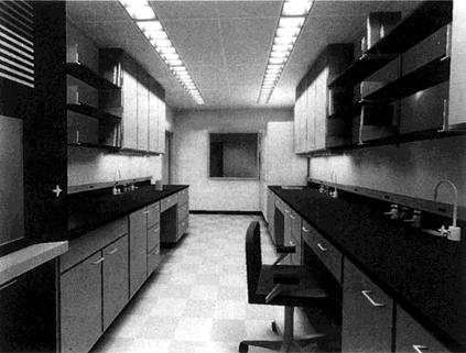
Figure 11.2: An interior design study. Image courtesy of David L. Munson Hellmuth Obata & Kassabaum Architects Inc.
by the lack of computing power typically available to small architectural firms. The time it takes to produce an acceptable image is particularly crucial because architectural presentation is often the first, rather than the last, stage of the design process. Presentations of a design proposal to a potential client are thus developed under pressing time constraints. For image synthesis to play a role, it must be fast and dependable. Radiosity methods are only beginning to
provide this level of performance.
In spite of these issues, the compelling quality of radiosity images, the possibility of interactive walkthroughs, and the fact that it is physically based make radiosity an attractive alternative. An architectural design application using radiosity is shown in Figure 11.1 and in color plates 47 and 50. The images in Figures 11.2 and 11.3 were produced using software developed at the architectural firm of Hellmuth, Obata & Kassabaum, Inc.
11.1.2 Lighting Design
The accurate simulation of global illumination is also a useful tool for lighting designers. For conventional lighting situations, such as an office, designers often rely on tables, simple formulae or rules of thumb in deciding how many lighting fixtures to use and where to position them. For unique lighting designs, a threedimensional model may sometimes be constructed and lit. Specialized software
Radiosity and Realistic Image Synthesis |
334 |
Edited by Michael F. Cohen and John R. Wallace |
|
CHAPTER 11. APPLICATIONS AND RESEARCH
11.1 APPLICATIONS
Figure 11.3: A second view from the same interior design study. Image courtesy of David L. Munson Hellmuth Obata & Kassabaum Architects Inc.
is also becoming increasingly common. (Ward’s experimental Radiance package is a particularly sophisticated general purpose example [252].) Physically based global illumination models and algorithms provide the possibility of more general quantitative results as well as realistic images for aesthetic evaluation.
Lighting manufacturers have also begun to develop their own radiosity based lighting design tools, often with the goal of distributing software along with digital catalogues of luminaires to architectural and lighting design firms. Companies ranging from Toshiba Lighting and Technology in Japan, to Philips Electronics and Zumtobel Licht GmbH in Europe (color plate 51) have begun to experiment with this technology.
Theatrical Lighting
Theatrical lighting is a special case of lighting design that has very particular requirements. Although light sources are limited to five or so basic types, a theatrical production typically uses hundreds of individual lights. These are turned on and off frequently in different combinations. The continuous variation of light intensity over time is often aesthetically important.
The circumstances under which the lighting for a particular production is designed are usually demanding. Sets are constructed at the last minute. As a result, the actual appearance of the lighted set cannot be fully evaluated until just
Radiosity and Realistic Image Synthesis |
335 |
Edited by Michael F. Cohen and John R. Wallace |
|
CHAPTER 11. APPLICATIONS AND RESEARCH
11.1 APPLICATIONS
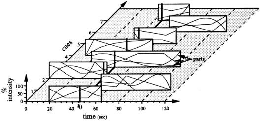
Figure 11.4: Part of a lighting specification for a production at the Metropolitan Opera House. Each light or group of lights has its own time history of intensity. Provided by Julie 0’B. Dorsey courtesy of the Metropolitan Opera.
prior to the first performance. Computer simulation thus seems ideally suited to the design of stage lighting.
Several features of the theatrical lighting design problem make radiosity a potentially useful tool. The model to be illuminated is normally static. The scene may need to be evaluated from a number of viewpoints throughout the audience seating. These views are taken from outside the scene, so there is a fairly well-defined limit to the shading detail required.
On the other hand, there are several aspects of the problem that require modifications to the conventional radiosity approach. For example, the light sources have very specific characteristics that must be modeled correctly. The sources are typically highly directional and thus quite different from ideal diffuse emitters handled by conventional radiosity. Dorsey [74fldescribes modified form factor formulae (similar to those discussed in Chapter 10).
Although the geometry of the scene is static, this is not true of the lighting. The complexity of the problem is suggested by the diagram in Figure 11.4, which specifies the lighting changes for different banks of lights over time for a production at the Metropolitan Opera House. Fortunately, most lighting changes involve changes in emitted power rather than repositioning or repointing of the light. The static positioning of lights allows the effect of various lights or combinations of lights to be computed independently. For any given lighting specification, the independent solutions can then be rapidly scaled appropriately and summed to provide the total radiosity [73fl.
Dorsey’s program includes extensive tools for lighting specification (see
Radiosity and Realistic Image Synthesis |
336 |
Edited by Michael F. Cohen and John R. Wallace |
|
CHAPTER 11. APPLICATIONS AND RESEARCH
11.1 APPLICATIONS
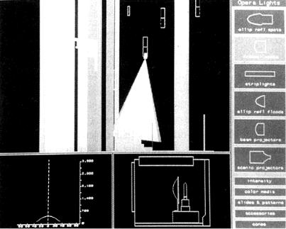
Figure 11.5: The specification and pointing of lights in an application for operatic lighting design. Courtesy of Julie 0’B. Dorsey Program of Computer Graphics Cornell University.
Figure 11.5) and for viewing the solution. Color plates 53 and 54 and the image on the back cover show results generated by this application. The solutions were computed using progressive radiosity with ray traced form factors. Rendering was performed using a stochastic ray tracer. Texture mapping (discussed in Chapter 9) has also been used very effectively to add detail during rendering.
Lighting Optimization
Kawai et al. [137] have developed techniques that invert the radiosity simulation paradigm. Given a geometric description of an environment and the illumination requirements or a desired appearance for the scene, their algorithm addresses the question of how the lighting parameters should be set to achieve these goals. They describe a method for designing the illumination in an environment by applying optimization techniques to a radiosity-based image synthesis system. The user is able to specify the illumination in terms of subjective criteria such as “pleasantness” and “privateness.” Other goals such as minimizing total energy consumption or maintaining a minimum illumination on a work surface can also be specified. An optimization of lighting parameters is then performed
Radiosity and Realistic Image Synthesis |
337 |
Edited by Michael F. Cohen and John R. Wallace |
|
CHAPTER 11. APPLICATIONS AND RESEARCH
11.1 APPLICATIONS
based on the user-specified constraints and objectives for the illumination of the environment. The system solves for the “best” possible settings for light-source emissivities, element reflectivities, and spot-light directionality parameters.
11.1.3 Remote Sensing
Satellite images of visible and near-infrared light are frequently used to survey land use and resources. From the point of view of a satellite, a forest or other region of vegetation is a “surface” with a characteristic BRDF that determines its appearance under various observation conditions. One way of determining this BRDF is to perform a series of measurements in the field.
Computer simulation provides an alternative means of determining the BRDF For example, to compute a BRDF for a forest canopy, a simplified model of the canopy specifying its interaction with light can be constructed and evaluated. One such model treats the canopy as a system of homogeneous volume elements with a certain density. A model of radiative transfer is then used to compute the interaction of light with the volumes [99].
Radiosity methods have also been applied to this problem [34, 94]. Since radiosity requires explicitly modeled geometry, it can support a detailed canopy model constructed of individual leaves. It thus provides more control over the characteristics of the simulated vegetation. The view-independence of the radiosity solution is also an advantage. Although the reflectivity of any individual leaf is treated as ideal diffuse, the BRDF for the canopy as a whole can be highly directional, due to varying occlusion and anisotropic leaf orientation. Following the radiosity solution, the BRDF can be evaluated for a range of view angles by rendering an image of the solution for each view angle. The radiance is averaged over the pixels of the image, and the BRDF for that view angle is then determined by the ratio of the radiance to the incident irradiance.
Borel et al. [34] suggest other applications for radiosity in remote sensing, including modeling the scattering of light between topographic features like the sides of valleys and the effect of clouds on illumination of land features. They also envision the use of radiosity in plant biology to simulate light transport and photosynthesis in plants.
11.1.4 Visual Shape Understanding
The need for a better understanding of visual perception in developing more efficient and accurate image synthesis algorithms has surfaced a number of times in this book. Interestingly, image synthesis itself can play an important part in improving the understanding of visual perception. For example, texture mapping and ray tracing have been applied in research into visual shape understanding in experiments to explore how the eye and brain extract information about
Radiosity and Realistic Image Synthesis |
338 |
Edited by Michael F. Cohen and John R. Wallace |
|
CHAPTER 11. APPLICATIONS AND RESEARCH
11.1 APPLICATIONS
geometric shape from the visual field.
Information about geometric shape is provided by binocular vision, as well as by cues such as texture, shading, cast and received shadows, and highlights [29, 96, 128, 129, 274]. Wanger [250] has used texture mapping and cast shadows to explore the importance of these and other cues to positioning tasks in computer graphics applications. Synthesized images are valuable in investigating shape and positioning cues because they allow controlled experiments in which image features are isolated. For similar reasons, image synthesis is useful in testing algorithms and devices for machine vision. The machine vision field has relied mainly on edge finding algorithms for object recognition, but researchers have also investigated “shape from shading” techniques [128].
Although there is some understanding of how direct illumination provides shape information, illumination due to interreflected light complicates the problem [179]. Forsyth and Zisserman [85] have explored the applicability of the radiosity equation as a model of global illumination for shape perception. They argue that discontinuities in the radiance function, caused by shadows or surface creases, provide stronger shape cues than the smooth variation of the function due to surface curvature. The availability of discontinuity meshing may provide a means to investigate this possibility. Parker et al. [178] have developed radiosity code specifically for experimentation in shape understanding.
11.1.5 Infrared Signature Analysis
The goal of infrared signature analysis is the recognition of vehicles or other objects by their characteristic appearance or signature in images produced by infrared imaging systems. Computer simulation provides a valuable way to generate these signatures. An example of a simulated infrared image is shown in Figure 11.6.
An infrared sensor detects radiance leaving an object due to emission and reflection. Infrared imaging requires a complete heat transfer model incorporating the processes of convection, conduction, and radiative transfer (with shadowing) for ideal diffuse and specular BRDFs. Heat sources include engines, exhaust, solar illumination, and sky illumination.
Many of these requirements are outside of the concerns of normal image synthesis. However, the radiative transfer component can benefit from algorithms developed for radiosity as applied to image synthesis, particularly algorithms for computing form factors. For example, the hemicube algorithm has been used by Johnson et al. [133] for this application.
Radiosity and Realistic Image Synthesis |
339 |
Edited by Michael F. Cohen and John R. Wallace |
|