

Cohen M.F., Wallace J.R. - Radiosity and realistic image synthesis (1995)(en)
.pdfCHAPTER 8. MESHING
Chapter 8
Meshing
The general strategies for automatic meshing described in the previous chapters determine where and when to subdivide, but not how to subdivide. The actual mechanics of subdividing geometry will be addressed in this chapter.
Basic subdivision techniques are addressed first. These are useful both for producing an initial uniform mesh as well as for further refining a mesh by adaptive subdivision. A priori algorithms for determining mesh boundaries that correspond to discontinuities in the radiosity function will also be discussed.
Meshing algorithms are best constructed on an underlying topological data structure that efficiently represents the adjacencies between nodes, edges and elements. The basic characteristics of such data structures and how they can be applied to meshing will be described.
Finally, several alternatives to meshing have been developed in order to avoid some of the complexities of surface subdivision. These approaches will be examined both for their own sake as well as for the somewhat different light they shed on the overall problem of approximating the radiosity function.
8.1 Basic Subdivision Techniques
A wide variety of subdivision techniques has been developed for finite and boundary element analysis. Surveys have organized these techniques according to a variety of taxonomies [92, 146, 211]. For our purposes, subdivision techniques are broadly classified according to whether or not the mesh topology is predetermined.
Algorithms that use a predetermined topology subdivide by mapping a mesh template to the geometry. The template is a predefined subdivision into standard elements, such as a rectangular grid. The essential step of the meshing process consists of determining a mapping between the geometry and the template. The alternative, in which the topology is not predetermined, is to decompose the geometry into elements by locating and connecting nodes according to some procedure. As a trivial example, a polygon might be subdivided by connecting its vertices to form triangles.
Radiosity and Realistic Image Synthesis |
209 |
Edited by Michael F. Cohen and John R. Wallace |
|

CHAPTER 8. MESHING
8.2 MESH TEMPLATE METHODS
Figure 8.1: Subdivision using a mesh template.
Both basic subdivision approaches have been used for radiosity and are described further in the following sections.
8.2 Mesh Template Methods
8.2.1 Grid Superposition
The most direct way of mapping a mesh template to the geometry is simply to superimpose the template on the geometry. The geometry is then split along the grid lines to create the mesh (see Figure 8.1). The chief advantage of this approach is that it generates perfectly regular, well-shaped elements on the interior of the geometry.
Unfortunately, the “cookie-cutter” approach frequently generates unacceptable elements where the template intersects the boundary. Elements are often poorly shaped, with low aspect ratios, concavities or extra vertices. Element shape can be improved by smoothing the mesh (as in section 8.4), but smoothing cannot eliminate extra vertices.
Grid superposition schemes improve on the cookie-cutter approach by providing special handling for elements near the boundary. For example, elements of the template that contain pieces of the boundary may be partially collapsed to eliminate extra vertices.
Baum et al. [18] describe an alternative in which the mesh template is used to create only those elements that lie fully inside the boundary. The region between the boundary and the interior elements is then triangulated.1
1This subdivision technique was first described by Rockwood as a means of tesselating trimmed spline surfaces for display [194].
Radiosity and Realistic Image Synthesis |
210 |
Edited by Michael F. Cohen and John R. Wallace |
|

CHAPTER 8. MESHING
8.2 MESH TEMPLATE METHODS
Figure 8.2: Subdivision using a template for interior elements and triangulation to connect to boundary.
In the first step of Baum’s approach the template is superimposed on the geometry. The grid is traversed and elements are created only where all four corners of the grid square are well inside the boundary. Grid corners that are inside but very close to the boundary are rejected, since they may cause poorly shaped elements during the triangulation step. Next, the boundary is subdivided at regular intervals corresponding to the desired mesh density. Finally, the region between the subdivided boundary and the internal elements is triangulated (see Figure 8.2).
Since the triangulation will link element edges to all boundary vertices, small boundary features are incorporated into standard three-sided elements. However, if the boundary contains features or edges that are much smaller than the target element size, triangulation will often result in poorly shaped elements and a poorly graded mesh (see Figure 8.3).
In general, the graceful incorporation of small boundary features requires a nonuniform mesh. Producing a well-graded, nonuniform mesh requires greater control over element size than is provided by a uniform template. However, template methods can be generalized to produce nonuniform meshes by using an adaptive, variable-size template [211].
8.2.2 Template Mapping
The use of a template is simplified if the template can be mapped to fit the geometry exactly. For example, a rectangular template can be mapped exactly
Radiosity and Realistic Image Synthesis |
211 |
Edited by Michael F. Cohen and John R. Wallace |
|

CHAPTER 8. MESHING
8.2 MESH TEMPLATE METHODS
Figure 8.3: Small features of the geometry may cause poorly shaped elements.
to fill a convex quadrilateral. The mapping in this case is the same as for the bilinear isoparametric element described in Chapter 5. Once the mapping is obtained, a set of elements corresponding to the template can be turned into an actual mesh simply by transforming the parametric coordinates for each node to geometric coordinates. More general mappings can be used to handle regions with curved boundaries or with more than four sides [235], although these have not been applied to radiosity to date.
Although mapping increases the range of geometries that can be meshed with template subdivision, there are limitations. The mapping may introduce severe distortions, resulting in a nonuniform mesh of poorly shaped elements. In addition, although a conformal mapping does exist between any two simply connected regions with an equal number of vertices, directly mapping geometries with more than four sides can be complicated.
8.2.3 Multiblocking
An alternative when the geometry is too complicated or is concave is to subdivide the geometry into simpler regions or blocks first. Templates can then be mapped directly to each of the regions.
Cohen et al. [61] use multiblocking with mapped templates in an early radiosity implementation. Surfaces are subdivided into convex quadrilaterals and triangles by connecting vertices of the geometry These regions are then subdivided into quadrilateral or triangular elements by splitting the edges in half
Radiosity and Realistic Image Synthesis |
212 |
Edited by Michael F. Cohen and John R. Wallace |
|

CHAPTER 8. MESHING
8.2 MESH TEMPLATE METHODS
Figure 8.4: Subdivision with mapped elements. The geometry is first split into simple shapes. In Cohen’s algorithm, the boundaries are then bisected and new vertices joined to form elements. Subdivision proceeds recursively as needed.
and joining them across the interior to create four elements. Finer mesh densities are obtained by continuing the subdivision recursively until the desired element size is reached (see Figure 8.4). Splitting edges at the midpoint guarantees that new elements created on either side of the edge will be conforming.
When the initial blocks are obtained by joining the vertices of the original geometry, the blocks may sometimes have extreme shapes that produce highly distorted mappings. These can be avoided by adding new vertices on the boundary or the interior of the geometry. As noted in [146], however, once such an algorithm is available for the initial subdivision, there is little reason not to use it to produce the entire mesh.
Radiosity and Realistic Image Synthesis |
213 |
Edited by Michael F. Cohen and John R. Wallace |
|
CHAPTER 8. MESHING
8.2 MESH TEMPLATE METHODS
8.2.4 Adaptive Subdivision with Templates
Once the mapping has been established, a mesh produced using a template can be refined during adaptive subdivision by applying the template again to elements requiring further subdivision. In Cohen’s quadtree subdivision algorithm, for example, quadtree subdivision is invoked again following the initial solution to refine elements where needed.
As a means of a posteriori mesh refinement, mapped templates (of which the quadtree scheme is the most common example for radiosity) have the disadvantage that the placement of element boundaries is inflexible. New element edges cannot be oriented to distribute the error as evenly as possible. As a result, adaptive subdivision using template mapping may require more elements than necessary to achieve a certain accuracy.
Template mapping approaches, like the quadtree algorithm, also tend to generate nonconforming elements in regions of changing mesh density. For example, when neighboring elements are subdivided to different levels, quadtree subdivision creates T-vertices. If the node at the T-vertex is not shared by the larger neighboring element, a discontinuity in the approximation will be introduced along that edge, since the interpolated value at that point will generally be different from the value computed at the node for the same point (see Figure 8.5). On the other hand, if the node at the T-vertex is shared with the larger element, the large element is no longer well shaped, since it contains 5 nodes, one of which is at the apex of edges forming a l80-degree angle.
Quadtree algorithms have employed several techniques for handling T- vertices Cohen et al. create special nodes at T-vertices, sometimes called slave nodes in the finite element literature. The function is not actually evaluated at slave nodes. Instead, the value at a slave node is interpolated (linearly, in this case) from the nodes of the largest element sharing that edge (nodes A and B in Figure 8.6). This allows interpolation on the larger element to ignore the slave nodes without introducing discontinuities.
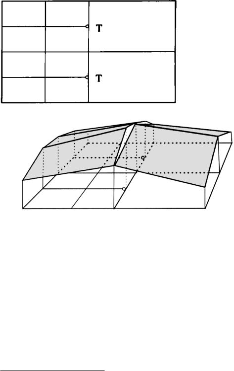
Baum, et al. [18] describe an alternative way of handling T-vertices. Nodes at T-vertices are shared by all elements surrounding the vertex and the function is evaluated at the node. To maintain correct element shape, the larger element is then triangulated to form smaller properly shaped elements (see Figure 8.7). The resulting modified hierarchy is called a tri-quadtree.
The extra triangulation in the tri-quadtree is not a permanent part of the mesh. The triangulation of a problem element is used only when needed for linear interpolation. If further adaptive subdivision is required later in the solution, it will be performed on the original element, not the triangulation.
Adaptive subdivision using a quadtree often produces poorly graded meshes. Figure 8.8 shows an example in which a large element is adjacent to a highly
Radiosity and Realistic Image Synthesis |
214 |
Edited by Michael F. Cohen and John R. Wallace |
|
CHAPTER 8. MESHING
8.2 MESH TEMPLATE METHODS
Figure 8.5: Discontinuity introduced by incorrectly handled T-vertices
subdivided region. Triangulation of the large element in this case will produce triangles with a poor aspect ratio. The use of slave nodes may produce a visible artifact along the long edge, due to its close proximity to nodes at which the function is actually evaluated.
Better mesh grading can be achieved by requiring a balanced or restricted quadtree [18, 211]. Neighboring elements in a restricted quadtree are allowed to differ by only one level of subdivision. A balanced tree can be achieved by checking the neighbors of an element when it is subdivided, and by subdividing those neighbors recursively.2
2Algorithms for performing this and other operations on quadtrees can be found in Samet [204].
Radiosity and Realistic Image Synthesis |
215 |
Edited by Michael F. Cohen and John R. Wallace |
|

CHAPTER 8. MESHING
8.3 DECOMPOSITION METHODS
Figure 8.6: T-vertices treated as slave nodes.
Figure 8.7: Tri-quadtree used to eliminate t-vertices.
8.3 Decomposition Methods
Mapped template methods are efficient and produce well shaped elements for simple geometries. However, their limited flexibility is a drawback when subdividing more complicated geometries and during a posteriori mesh refinement.
Subdivision methods that decompose the geometry into elements piece by piece provide greater flexibility. There are two basic approaches to this decomposition: the nodes and elements can be produced at the same time using a single procedure or the nodes can be produced first and then connected to form edges in an independent step.
Radiosity and Realistic Image Synthesis |
216 |
Edited by Michael F. Cohen and John R. Wallace |
|

CHAPTER 8. MESHING
8.3 DECOMPOSITION METHODS
Unrestricted quad-tree |
Restricted quad-tree |
Figure 8.8: Use of restricted quadtree to improve mesh grading.
8.3.1 Nodes–Elements–Together Decomposition
In this approach, the geometry is subdivided by creating nodes and joining them with edges to generate new elements one by one. Subdivision can be performed recursively, first subdividing the entire geometry into initial elements, then splitting those elements again until the desired element size is reached. During subdivision, new nodes can be positioned according to criterion selected to produce a mesh with certain density or smoothness properties. Chew [53] and Watson [256] describe incremental Delaunay triangulation algorithms of this type. Alternatively, subdivision may proceed from the boundary inward, splitting off triangles one by one until the entire geometry is meshed.
8.3.2 Decomposition by Recursive Splitting
Campbell and Fussell [43] subdivide surfaces by recursive splitting using a twodimensional binary space partition (BSP) tree. The BSP-tree allows arbitrary orientation of element edges (see Figure 8.9). Elements are created by splitting larger regions along an arbitrary edge. The ability to incorporate arbitrarily oriented edges allows Campbell and Fussel to include previously determined discontinuity boundaries into the mesh.
Campbell and Fussell also use the flexibility of BSP subdivision advantageously during adaptive subdivision. The edge used to split an element is oriented to minimize the variation in radiosity over the new elements. Using optimization techniques, Campbell and Fussell locate the global maximum and minimum for the element and subdivide halfway between the two extreme points
Radiosity and Realistic Image Synthesis |
217 |
Edited by Michael F. Cohen and John R. Wallace |
|

CHAPTER 8. MESHING
8.3 DECOMPOSITION METHODS
Figure 8.9: Hierarchical surface subdivision using a BSP tree (after Campbell, 1990).
along an edge perpendicular to the line joining the extrema.
Although the BSP-tree is more flexible than the quadtree, it is also more difficult to maintain conforming elements with the bsp-tree. T-vertices occur frequently, since neighboring elements are split along edges that are not likely to meet at a common node. Campbell and Fussell treat T-vertices as slave nodes. They also recommend a final clean-up pass following adaptive subdivision, during which the tree is balanced by subdividing elements with highly subdivided neighbors and those with a poor aspect ratio.
Lischinski and Tampieri [154], who also use a bsp-tree to represent surface subdivision, avoid the clean-up pass by simultaneously maintaining a data structure representing the mesh topology. Nodes of the BSP-tree point to edges in a winged-edge data structure. T-vertices can then be eliminated using a simple trianlgulation pass.
8.3.3 Decomposition by Advancing Front
In contrast to recursive splitting, decomposition may also proceed from the boundary inward, splitting off finished elements one at a time. This is sometimes called the advancing front method, because the forward boundary of the meshed region is progressively advanced into the unmeshed region until the entire geometry is subdivided [92]. Algorithms of this type are distinguished by the technique with which the front is advanced. For example, the front may be searched to locate the smallest angle, which is then incorporated into a new triangular element and split off from the unmeshed region (see Figure 8.10). The advancing front method is also known as paving when it is used to subdivide
Radiosity and Realistic Image Synthesis |
218 |
Edited by Michael F. Cohen and John R. Wallace |
|